





Pole Mounted Transformer
Rated Capacity: 5–167 kVA (Single-phase); 30–315 kVA (Three-phase)
Primary Voltage: 2.4–34.5 kV (Depending on System Connection)
Secondary Voltage: 120/240 V, 208Y/120 V, 480Y/277 V, 400/230 V or customized
Frequency: 50 Hz / 60 Hz
Cooling Method: ONAN (Mineral Oil) / KNAN (Natural Ester)
Winding Material: Copper / Aluminum
Core Material: Grain-Oriented Silicon Steel
Protection Configuration: Conventional / CSP (Selected Single-phase Models)
Standards: IEEE C57.12.20, IEEE C57.12.00, IEC 60076 (As Applicable)
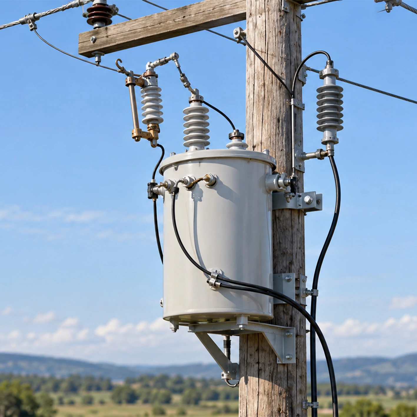
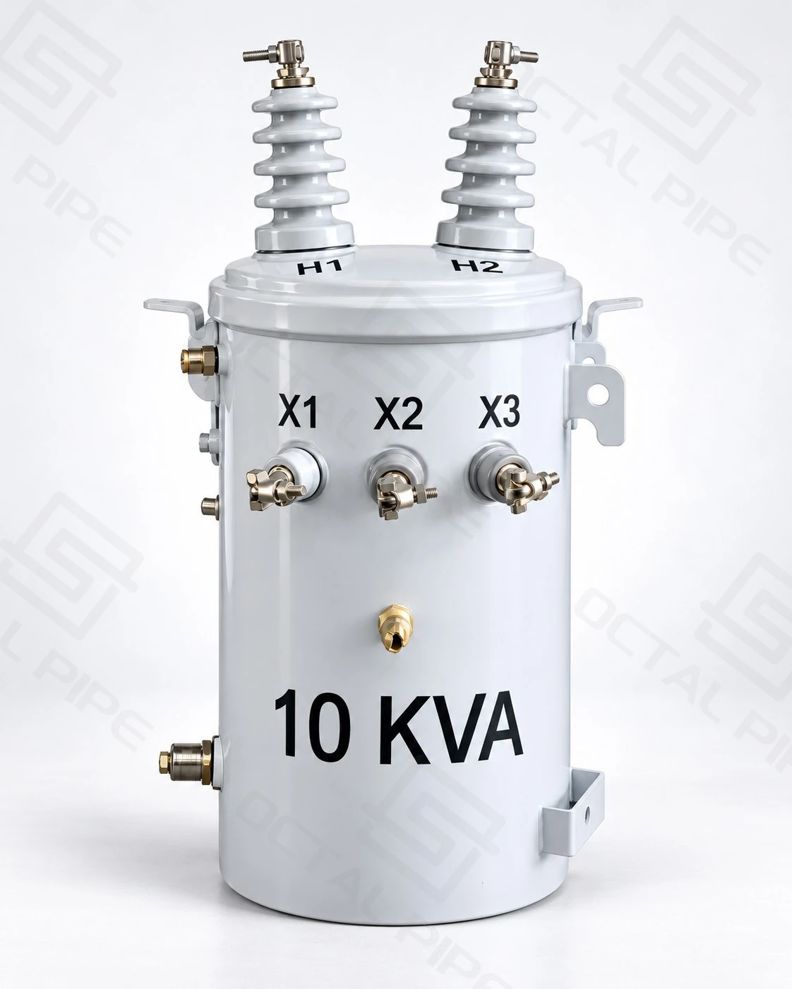
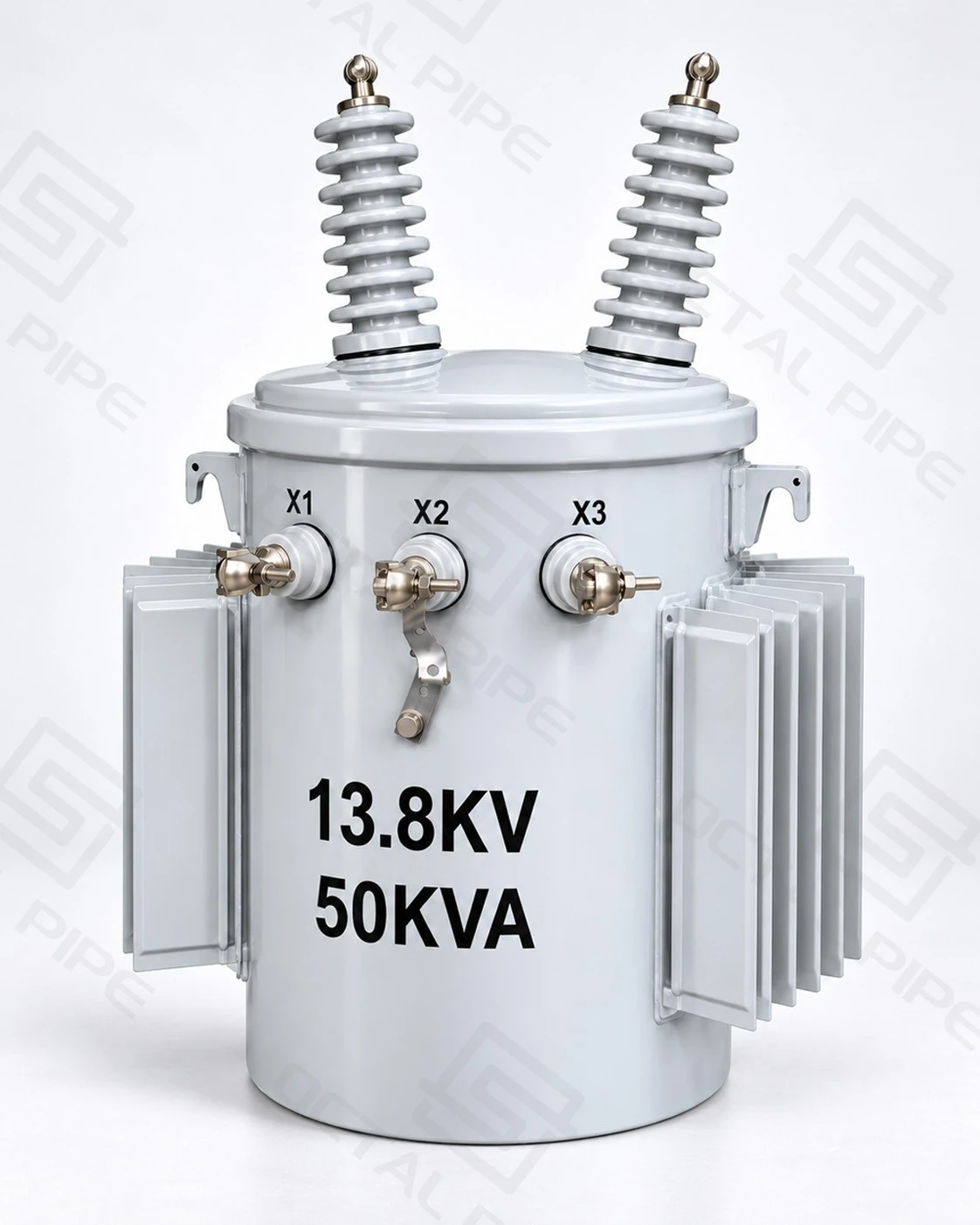
Pole Mounted Transformer is a distribution transformer designed for installation on utility poles. Most units use a liquid-immersed core and winding assembly housed in a sealed steel tank. Single-phase transformers typically have a cylindrical tank secured to the pole with mounting brackets, while three-phase installations may use one three-phase transformer or a bank of three single-phase units.
Pole mounted transformers reduce medium-voltage electricity to the lower voltages required by residential, agricultural, commercial and light industrial loads. They are commonly installed along overhead distribution networks to supply electricity to individual buildings or multiple locations connected to a distribution feeder.
Common configurations cover 5–167 kVA for single-phase transformers and 30–315 kVA for three-phase transformers, with primary voltage ratings selected to match the distribution network. Mineral oil and ester-based insulating fluids are available, together with different bushing arrangements, protective devices and mounting structures.
Pole Mounted Transformer Specifications
Pole mounted distribution transformers are manufactured in different electrical and mechanical configurations to suit ANSI/IEEE and IEC distribution networks. Capacity, voltage ratio, insulation level and mounting arrangement are selected together because the transformer must meet both the electrical requirements of the feeder and the physical limitations of the supporting structure.
| Parameter | Specifications |
|---|---|
| Product Type | Single-phase / Three-phase Pole Mounted Distribution Transformer |
| Rated Capacity | Single-phase: 5–167 kVA; Three-phase: 30–315 kVA |
| Primary Voltage | 2.4–34.5 kV for common IEEE designs; 6.6, 11, 22 and 33 kV for typical IEC distribution applications |
| Secondary Voltage | Single-phase: 120/240 V, 240/480 V; Three-phase: 208Y/120 V, 400/230 V, 415/240 V, 480Y/277 V or specified alternatives |
| Rated Frequency | 50 Hz / 60 Hz, according to the network |
| Cooling Method | ONAN (Oil Natural Air Natural) |
| Core Material | Grain-Oriented Electrical Steel; Amorphous Metal Core on selected designs |
| Winding Material | Copper / Aluminum |
| Insulating Fluid | Mineral Oil / Natural Ester / Specified Ester Fluids |
| Temperature Rise | Commonly 55°C or 65°C winding rise, according to the applicable design |
| Tap Changer | De-energized taps where specified; ±2 × 2.5% is a common arrangement |
| Protection Configuration | Conventional / Completely Self-Protected (CSP), where available |
| HV Connections | One or two primary bushings for applicable single-phase designs; three-phase connections according to winding configuration |
| Tank Construction | Welded Steel Tank / Sealed Liquid-Filled Construction |
| Mounting Arrangement | Pole Brackets / Crossarm or Platform Mounting |
| Main Standards | IEEE C57.12.20, IEEE C57.12.00, IEEE C57.12.90, IEC 60076 Series |
| Applications | Rural Distribution, Residential Supply, Agricultural Facilities, Commercial Loads and Light Industrial Power |
The listed values represent common product configurations. The actual primary winding voltage, secondary connection, insulation level, dimensions and operating weight depend on the selected transformer design.
Pole mounted transformer prices generally range from approximately USD 800 to 5,000 per unit for conventional export configurations. A small single-phase unit is usually less expensive than a larger three-phase transformer with higher voltage ratings and additional protection equipment. Copper windings, ester insulating fluids, special efficiency requirements and utility-specific accessories can also increase the price. Larger or specially engineered models are quoted individually.

Pole Mounted Transformer Standards
Pole mounted transformers are designed according to the applicable IEEE or IEC standards, depending on the destination market, operating frequency, voltage class and utility requirements. These standards cover electrical performance, insulation, mechanical construction and testing.
| Standard | Scope |
|---|---|
| IEEE C57.12.20 | Electrical, dimensional and mechanical requirements for single-phase and three-phase overhead-type distribution transformers |
| IEEE C57.12.00 | General requirements for liquid-immersed distribution, power and regulating transformers |
| IEEE C57.12.90 | Test methods for winding resistance, voltage ratio, losses, impedance, dielectric performance and other electrical characteristics |
| IEEE C57.12.31 | Enclosure coating integrity for pole-mounted equipment in conventional environments |
| IEEE C57.12.30 | Enclosure integrity requirements for pole-mounted equipment installed in coastal environments |
| IEC 60076 Series | General transformer requirements, temperature rise, insulation tests, short-circuit withstand and related technical requirements |
IEEE C57.12.20-2023 covers 60 Hz overhead-type distribution transformers rated up to 500 kVA, with high-voltage ratings not exceeding 34.5 kV. This is the scope of the standard, not a universal capacity rating for every pole-mounted installation. The maximum practical transformer size also depends on the pole structure, mounting equipment and utility installation requirements.
For IEC-based projects, the relevant IEC 60076 series governs electrical design and testing. IEC 60076-2 addresses temperature rise in liquid-immersed transformers, while IEC 60076-3 covers insulation levels and dielectric testing.
Single-Phase And Three-Phase Pole Mounted Transformers
Both configurations are used in overhead distribution systems, but their winding connections, load characteristics and mounting arrangements differ.
Single-Phase Pole Mounted Transformers
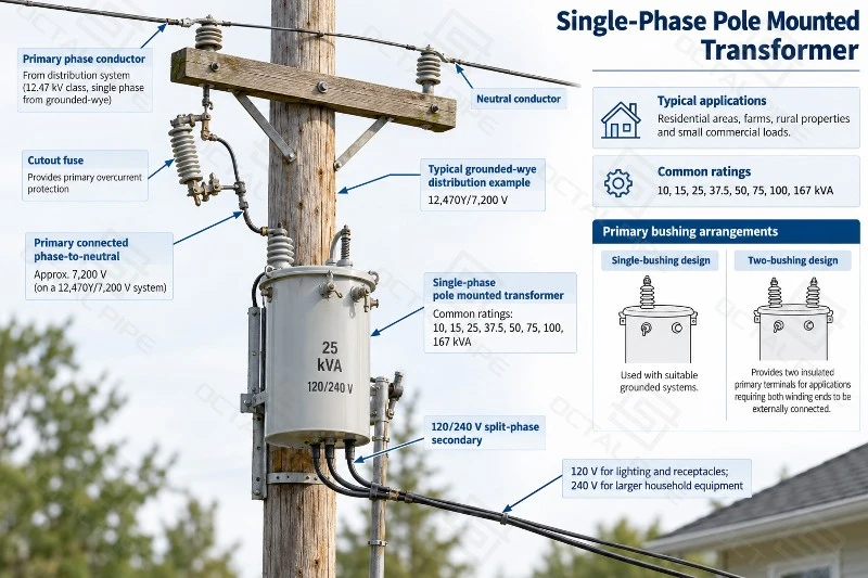
A single-phase pole mounted transformer normally supplies single-phase electricity to residential buildings, farms, rural properties and smaller commercial loads. Common ratings include 10, 15, 25, 37.5, 50, 75, 100 and 167 kVA, although smaller units are also available.
On a North American grounded-wye distribution network, a transformer may be connected between a phase conductor and the system neutral. For example, a feeder operating at 12,470Y/7,200 V has approximately 7,200 V between phase and neutral. A transformer connected in this arrangement uses a primary winding rated for the appropriate phase-to-neutral voltage, even though the feeder is commonly identified as a 12.47 kV system.
A 120/240 V split-phase secondary provides 120 V connections for lighting and general outlets, together with 240 V for higher-voltage household equipment. Different secondary arrangements are available for industrial or regional distribution requirements.
The primary bushing arrangement depends on the network connection. Single-bushing designs are used with suitable grounded systems, while two-bushing designs provide two insulated primary terminals for applications requiring both winding ends to be externally connected.
Three-Phase Pole Mounted Transformers
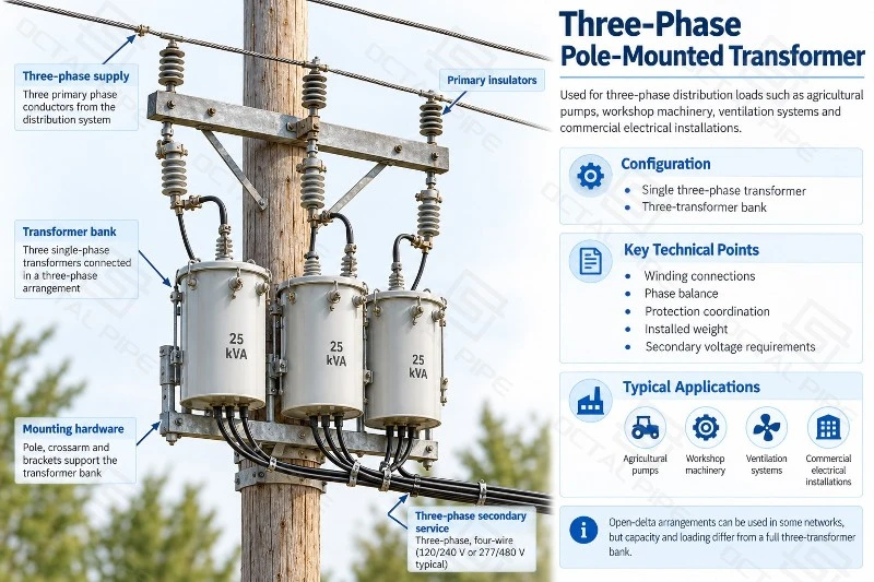
A three-phase pole mounted transformer supplies three-phase loads such as agricultural pumps, workshop machinery, ventilation systems and commercial electrical installations.
One option is a single three-phase transformer containing the complete three-phase core and winding assembly in one tank. Another is a three-transformer bank, formed by connecting three single-phase units into an appropriate three-phase arrangement.
A single three-phase tank provides an integrated assembly and may reduce the number of separate tanks and mounting components. A bank of single-phase transformers offers individual-unit replacement possibilities and allows utilities to use standardized single-phase equipment.
The choice affects more than the number of tanks. Winding connections, phase balance, protection coordination, total installed weight and secondary voltage requirements must be compatible with the distribution system. In some networks, an open-delta arrangement can be used with two single-phase transformers, but its capacity and loading characteristics differ from those of a full three-transformer bank.
Construction And Protection
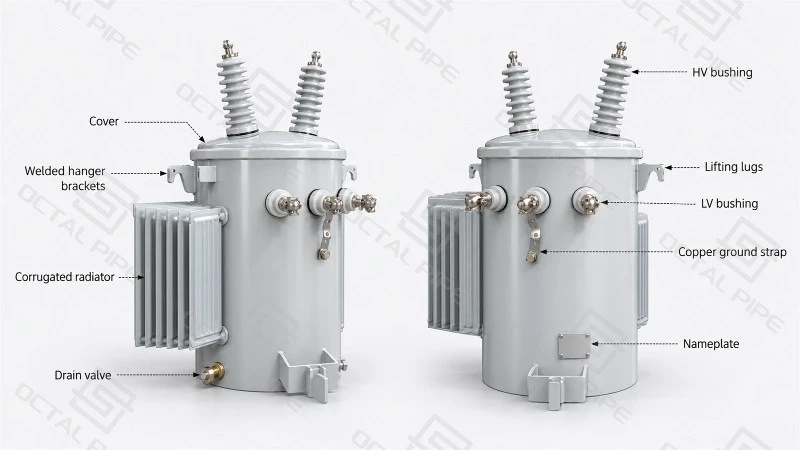
A typical pole mounted transformer consists of a magnetic core, insulated windings, steel tank, insulating liquid, bushings and pole-mounting hardware. The core and winding assembly is immersed in insulating fluid, which provides dielectric insulation and transfers heat from the active parts to the tank.
Grain-oriented electrical steel is commonly used for transformer cores because its magnetic characteristics help control no-load losses. Amorphous metal cores are available in selected designs where lower core losses are required. Copper or aluminum conductors are used for the windings, with insulation arranged to withstand normal operating voltage and the specified dielectric tests.
The steel tank supports the active assembly and protects it from moisture and outdoor contamination. Welded joints, cover seals and bushing gaskets form part of the liquid-containment system. The design also accommodates changes in insulating-liquid volume as operating temperature rises and falls.
Bushings And External Connections
High-voltage bushings provide insulated connections between the overhead feeder and the transformer windings. Low-voltage bushings carry power to the outgoing service conductors.
Porcelain and polymer bushings are used according to voltage class, equipment design and utility requirements. Terminal dimensions and connector materials must accommodate the selected conductors, including copper or aluminum connections where specified.
The tank normally incorporates grounding provisions, lifting points and mounting brackets. Depending on the model, additional fittings may include a pressure-relief device, oil-level indication, drain connection or sampling provision.
Conventional And CSP Protection
Conventional pole mounted transformers generally rely on separately installed protective equipment. A primary fuse cutout can isolate the transformer during specified fault conditions, while a surge arrester limits transient overvoltages associated with lightning and switching events.
A Completely Self-Protected (CSP) transformer incorporates selected protective functions into the transformer assembly. Depending on the design, these can include an internal primary fuse, low-voltage circuit breaker and surge arrester. Some configurations provide external operating handles or overload indication.
CSP protection arrangements differ by manufacturer, capacity and voltage class. They do not eliminate the need to assess upstream fault levels or coordinate protection with the distribution feeder.
Electrical Performance And Operating Losses
The electrical performance of a pole mounted transformer is determined by its rated capacity, voltage ratio, losses, short-circuit impedance and thermal characteristics.
No-load loss occurs whenever the transformer is energized, even when no electricity is being delivered to connected equipment. It is mainly associated with magnetic losses in the core. Load loss is produced by current flowing through the windings and associated stray-loss mechanisms, increasing as the electrical load rises.
A reduction of 40 W in no-load loss represents approximately 350 kWh of electricity per year for a transformer energized continuously for 8,760 hours. Across a distribution network containing hundreds of continuously energized units, differences in core loss can have a measurable effect on annual energy consumption.
Electrical ratings also determine the current carried by the secondary terminals. For example, a 50 kVA single-phase transformer supplying 240 V has a rated secondary current of approximately 208 A. A 100 kVA three-phase transformer supplying 415 V line-to-line carries approximately 139 A per line at rated balanced load. These currents influence secondary terminal selection, conductor sizing and connection arrangements.
Short-circuit impedance affects voltage drop under load and the fault current available at the transformer secondary. Lower impedance generally allows higher prospective fault current, subject to the upstream system impedance. The measured impedance value alone does not establish the transformer's complete short-circuit withstand capability; winding mechanical design and the applicable withstand requirements must also be satisfied.
Pole mounted transformers generally use ONAN cooling, in which heat from the windings passes into the insulating liquid and is released through the tank surface to the surrounding air without pumps or fans.
Continuous loading capability depends on ambient temperature, winding temperature rise and cooling-surface area. At sites with high ambient temperatures or elevated altitude, a transformer may require a different thermal design or operating rating to maintain the specified temperature limits.
Manufacturing
Transformer manufacturing begins with the core and winding assembly. Core laminations are stacked and secured to maintain the required magnetic characteristics, while the windings are formed with controlled conductor placement, insulation thickness and electrical clearances.
The assembled windings and insulation are dried before oil filling. Moisture remaining in the solid insulation can reduce dielectric strength and contribute to insulation deterioration during operation. The drying and liquid-filling processes are therefore closely related to the transformer's long-term insulation performance.
The steel tank is fabricated and welded before the active assembly and specified accessories are installed. Welded joints, bushings, gaskets and cover connections are checked for mechanical integrity and leakage. The tank is then finished with the appropriate coating system for the installation environment.
After assembly, factory electrical testing measures winding resistance, voltage ratio, polarity or phase relationship, no-load loss, load loss and short-circuit impedance. Dielectric tests verify the insulation system against the specified electrical requirements.
Testing under the applicable methods of IEEE C57.12.90 or IEC 60076 may be supplemented by additional checks required for the project. Temperature-rise, lightning-impulse and short-circuit withstand tests are addressed through the applicable design or type-test requirements and are not automatically repeated on every manufactured unit.
Final inspection also examines the tank finish, bushings, mounting brackets, grounding connections, nameplate and installed accessories. Electrical test records and identification details are associated with the corresponding transformer serial number.
Pole Installation And Operating Conditions
The operating weight of a pole mounted transformer includes the tank, core and windings, insulating liquid and installed accessories. This weight acts on the pole through the mounting brackets or supporting platform.
A small single-phase unit may be mounted directly against the pole using a suitable hanger arrangement. Larger transformers and three-phase installations can require crossarms, platforms or two-pole supporting structures. The mechanical design must account for the equipment's weight, mounting geometry and environmental loads.
Outdoor installation also exposes the transformer to conditions that influence insulation and service life.
Electrical clearances depend on system voltage, the arrangement of nearby conductors and local utility requirements. Bushings, fuse cutouts and surge arresters need sufficient separation from adjacent energized equipment and grounded structures.
Wind, ice and seismic loads, where applicable, influence the supporting structure and mounting hardware. Locations with birds or other wildlife may require insulated bushing covers and additional wildlife-protection components to reduce contact-related faults.
For coastal locations, airborne salt can accelerate deterioration of exposed steel and fittings. Coating systems designed to meet IEEE C57.12.30 can be specified for suitable pole-mounted equipment, together with appropriate corrosion-resistant hardware.
High ambient temperature, solar exposure and restricted air movement can increase transformer operating temperature. Site altitude is another consideration because reduced air density affects heat dissipation and external insulation performance.
These installation conditions influence the suitability of the complete transformer arrangement, even when the required kVA and voltage ratings are otherwise correct.
Applications Of Pole Mounted Transformers
Pole mounted transformers are used mainly in distribution networks with overhead medium-voltage conductors, especially where ground-level equipment space is limited or loads are distributed over a large area.
Rural residential distribution commonly uses single-phase units to supply individual homes, groups of houses and community buildings. Positioning transformers along the medium-voltage feeder allows lower-voltage service conductors to reach nearby customers without extending a single low-voltage circuit over an excessive distance.
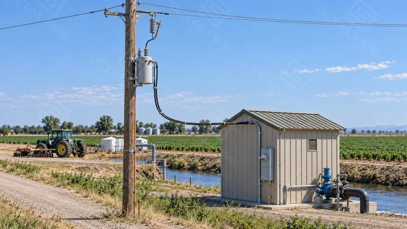
Agricultural installations may require electricity for irrigation pumps, grain-handling equipment, ventilation, refrigeration and farm buildings. Smaller installations can operate from single-phase supplies, while larger motor-driven equipment often requires three-phase power. Motor starting characteristics and operating duty influence the transformer capacity needed for these loads.
Commercial facilities such as roadside businesses, rural shops, small warehouses and service buildings can receive power from pole mounted distribution equipment where the existing electrical network uses overhead lines.
Light industrial sites may use three-phase transformers for workshops, processing equipment and auxiliary power systems. The equipment must accommodate the combined operating load and the voltage changes associated with starting motors or other intermittent high-current loads.
Remote communities and dispersed utility networks also use pole mounted transformers because individual units can be installed at suitable points along overhead feeders. Transformer positions and ratings can be selected to reflect the distribution of connected loads.

Why Choose Octal Pipe
At Octal Pipe, pole mounted transformer specifications are reviewed against the actual distribution system and installation conditions. The primary winding voltage, rated capacity, secondary connection, insulation level, bushing arrangement and protection equipment are checked together. On grounded-wye networks, the feeder's line-to-line voltage differs from the voltage applied across a phase-to-neutral transformer winding, making the correct primary voltage rating particularly important. For replacement units, existing mounting positions and conductor connections are also considered to minimize modifications during installation.
The equipment details are carried through to the project documentation. General arrangement drawings, nameplate data, factory test reports and packing information are matched to the transformer prepared for shipment. For repeat orders or replacement projects, previous specifications and drawings can be referenced to maintain the required electrical ratings, terminal arrangements and mounting details.
FAQ

01.Can a 60 Hz pole mounted transformer operate on a 50 Hz electrical network?
02.Why do some single-phase pole mounted transformers have one high-voltage bushing and others have two?
03.Can a pole mounted transformer supply equipment with a high motor-starting current?
04.Are pole mounted transformers shipped with insulating oil already inside?
Certifications

CE Certificate

ISO 9001 Certificate

API Q1 Certificate

ABS Certificate

AP-5L Certificate

API-5CT Certificate
Hot Tags: Pole Mounted Transformer, Pole Mounted Distribution Transformer, Single Phase Pole Mounted Transformer, Three Phase Pole Mounted Transformer
Previous
No InformationYou Might Also Like


Send Inquiry