




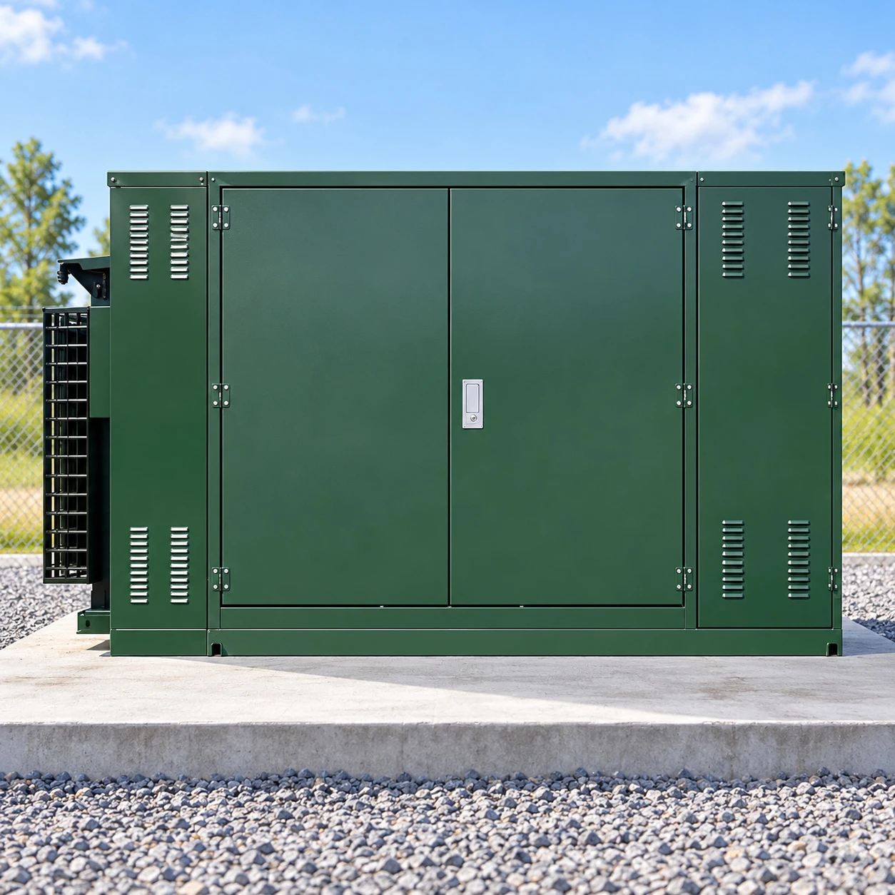
Pad Mounted Transformer
Rated Capacity: 15–250 kVA (Single-phase); 75–2,500 kVA (Three-phase)
Primary Voltage: 4.16, 12.47, 13.2, 13.8, 24.94, 34.5 kV
Secondary Voltage: 120/240 V, 208Y/120 V, 480Y/277 V, 600Y/347 V or customized
Frequency: 50 Hz / 60 Hz
Cooling Method: ONAN (Oil Natural Air Natural)
Feed Configuration: Radial Feed / Loop Feed
HV Construction: Dead-Front / Live-Front
Insulating Liquid: Mineral Oil / Ester Fluid
Winding Material: Copper / Aluminum
Tap Changer: De-energized, ±2 × 2.5% typical arrangement
Protection Options: Bay-O-Net Fuses, Current-Limiting Fuses, Loadbreak Switches, Surge Arresters
Standards: IEEE C57.12.00, IEEE C57.12.34, IEEE C57.12.38, IEEE C57.12.28
Pad Mounted Transformer units are commonly installed on concrete pads to convert medium-voltage electricity into the lower voltages required by residential developments, commercial buildings, industrial facilities and utility distribution networks. The transformer tank, high-voltage and low-voltage connections, protection components and lockable compartments form an integrated ground-mounted assembly suitable for outdoor installation.
Most pad mounted transformers use liquid-filled insulation, which provides electrical insulation and transfers heat from the core and windings to the tank and cooling surfaces. The high-voltage and low-voltage connections are housed in separate compartments, with radial-feed or loop-feed configurations available for different underground distribution networks.
Pad mounted transformers are available in various capacities, voltage ratings and electrical configurations. Key technical parameters include rated capacity, primary and secondary voltage, phase, frequency, impedance, BIL, cooling method and protection arrangement. Winding materials, insulating fluids and tap configurations also vary according to the electrical system and installation requirements.
Pad Mounted Transformer Specifications
Pad mounted transformers are available in single-phase and three-phase configurations for underground power distribution. Common models range from 15–250 kVA for single-phase units and 75–2,500 kVA for three-phase units, with larger three-phase designs available for higher-capacity applications. Voltage ratings, cable connections and cabinet arrangements vary across utility, commercial and industrial installations.
|
Parameter |
Typical Specifications |
|---|---|
|
Transformer Type |
Single-phase or three-phase, liquid-filled |
|
Rated Capacity |
Single-phase: 15–250 kVA; three-phase: 75–2,500 kVA, with larger ratings available |
|
Primary Voltage |
4.16, 12.47, 13.2, 13.8, 24.94 and 34.5 kV nominal systems; other ratings available |
|
Secondary Voltage |
120/240 V, 208Y/120 V, 480Y/277 V, 600Y/347 V and customized ratings |
|
Frequency |
60 Hz for conventional IEEE designs; 50 Hz for specified project configurations |
|
Cooling Method |
ONAN (Oil Natural Air Natural) |
|
Feed Configuration |
Radial feed or loop feed |
|
HV Construction |
Dead-front or live-front |
|
Insulating Liquid |
Mineral insulating oil or natural ester fluid |
|
Winding Material |
Copper or aluminum |
|
Tap Changer |
De-energized tap changer; ±2 × 2.5% is a common arrangement |
|
Protection Options |
Bay-O-Net fuses, current-limiting fuses, load-break switches and surge arresters |
|
Enclosure |
Lockable, tamper-resistant outdoor cabinet with separate HV and LV compartments |
For conventional distribution configurations, pad mounted transformer prices typically range from approximately USD 5,000 to 100,000 per unit (depending on rated capacity, voltage class, winding material, feed arrangement, insulating fluid and protection equipment). Larger-capacity transformers and utility-specific designs have individual project pricing.

Pad Mounted Transformer Standards
Pad-mounted transformer standards vary by phase arrangement, voltage class and utility requirements. In North America, IEEE C57.12.34-2022 covers three-phase, liquid-immersed, self-cooled transformers up to 10 MVA and 34.5 kV, while IEEE C57.12.38-2025 covers single-phase units up to 250 kVA, with high-voltage systems up to 34.5 kV and low-voltage ratings up to 480/240 V.
|
Standard |
Main Scope |
|---|---|
|
IEEE C57.12.34 |
Three-phase pad-mounted, compartmental-type, self-cooled distribution transformers |
|
IEEE C57.12.38 |
Single-phase pad-mounted, self-cooled distribution transformers up to 250 kVA |
|
IEEE C57.12.00 |
General requirements for liquid-immersed distribution and power transformers |
|
IEEE C57.12.28 |
Enclosure integrity for above-grade pad-mounted equipment |
|
IEEE C57.12.90 |
Test methods for liquid-immersed distribution and power transformers |
|
IEC 60076 series |
Applicable transformer design, insulation, testing and performance requirements in IEC-based projects |
IEEE C57.12.28 addresses cabinet coating and enclosure integrity for publicly accessible pad-mounted equipment energized above 600 V.
IEEE C57.12.00 covers general electrical and mechanical requirements for liquid-immersed transformers, while IEEE C57.12.90 defines test methods for winding resistance, voltage ratio, losses, impedance, dielectric performance, temperature and sound.
For IEC-based projects, the applicable IEC 60076 series may also be used, with the specific standards aligned with the destination market and utility requirements.
Compartmental Construction and Feed Configuration
The cabinet is one of the defining features of a pad mounted transformer. The transformer body remains inside the enclosure, while the connections are arranged in separate compartments that provide physical separation between the medium-voltage and low-voltage sides.
Dead-front construction places the high-voltage connections behind insulated separable connectors and bushings, reducing exposed energized parts when the compartment is accessed. This arrangement is widely used with underground cable systems. Live-front construction uses exposed high-voltage connections inside the accessible compartment and is generally associated with different connection and operating arrangements.
Radial-feed and loop-feed configurations serve different distribution layouts. A radial unit has one incoming primary circuit, while a loop-feed unit provides connection points for an incoming and outgoing underground circuit. Three-phase pad-mounted designs under IEEE C57.12.34 specifically address connector, bushing and terminal arrangements for both radial and loop-feed systems.
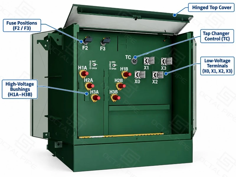
The cabinet can incorporate HV bushing wells, inserts, loadbreak switches, fuses, lightning arresters, grounding provisions, LV bushings and terminal connections according to the selected electrical arrangement. Door construction, locking provisions, hinges, lifting points and removable sills also form part of the mechanical design.
Protection, Taps and Insulating Fluid
Protection is integrated into the transformer configuration rather than treated as a separate cabinet accessory. A typical pad-mounted arrangement may include primary fusing, a loadbreak switch, pressure-relief equipment, oil-level indication and other monitoring devices. More complex installations can incorporate additional switching or protection equipment according to the fault level and distribution scheme.
Tap connections compensate for variations in the primary supply voltage and maintain the required secondary voltage. De-energized tap changers are common on distribution transformers and must be operated with the transformer isolated from the electrical system. The number and range of tap positions are defined by the transformer design and system voltage.
Mineral insulating oil remains a common liquid for conventional pad-mounted transformers. Ester-based insulating fluids are also available where fire performance, environmental considerations or project specifications make them appropriate. The choice of fluid affects the transformer tank, thermal design, filling procedure and applicable testing requirements.
Cooling and Thermal Performance
Heat generated in the transformer core and windings is transferred to the insulating liquid, which circulates naturally as its temperature rises. The heat then passes through the tank walls and external cooling surfaces into the surrounding air. This cooling arrangement is known as ONAN (Oil Natural Air Natural) and operates without oil pumps or cooling fans.
The tank and radiator surfaces provide the area needed to release heat during operation. Higher-capacity transformers generally require greater cooling surface area to accommodate increased losses. Some specially designed units also use forced-air cooling to increase heat dissipation and support higher loading.
Outdoor conditions affect the transformer's cooling performance. High ambient temperatures reduce the temperature difference between the tank and surrounding air, while direct sunlight can increase surface temperatures. Restricted airflow around the tank or radiators can further limit heat dissipation. At sites with elevated temperatures or high altitude, the cooling design and continuous load rating may need adjustment to keep oil and winding temperatures within the specified limits.
Losses, Impedance and Electrical Performance
A pad-mounted transformer's operating cost is influenced by both no-load loss and load loss. No-load loss occurs whenever the transformer is energized, while load loss increases with winding current. This distinction becomes significant in distribution networks where a transformer may remain energized around the clock even when the connected load varies substantially.
Short-circuit impedance affects voltage regulation, fault current and the behavior of transformers operating in parallel. The impedance value must therefore be considered together with the transformer's rated capacity and system voltage.
Efficiency figures also need to be associated with the applicable test conditions. As an example, U.S. DOE efficiency requirements for liquid-immersed distribution transformers use specified test procedures and reference loading conditions rather than treating a single efficiency percentage as universal.
A 200 W difference in no-load loss may appear small at the equipment level, but with 8,760 energized hours it represents 1,752 kWh per year before considering any difference in load losses. This is why core material, magnetic flux density and guaranteed loss values have practical importance in continuously energized distribution equipment.
Pad Mounted Transformer Manufacturing
Manufacturing quality is closely tied to the core, winding, tank and insulation system. Core laminations are assembled with controlled stacking and clamping, while the windings are manufactured to maintain the required electrical clearances and mechanical stability. The active assembly is dried before the insulating liquid is introduced, since moisture inside the insulation system can reduce dielectric performance.
The transformer tank is welded and inspected before painting or coating. Bushings, switches, fuses, gauges, pressure-relief devices and other specified accessories are then installed according to the approved arrangement drawing. The HV and LV compartments are checked against the required terminal positions and clearances before final assembly.
After assembly, factory testing measures winding resistance, voltage ratio, phase relationship, no-load loss, load loss and short-circuit impedance, and verifies dielectric withstand performance. These tests follow the applicable methods in IEEE C57.12.90, with additional inspections performed according to project requirements.
Test records are linked to the transformer serial number so that the delivered unit can be traced to its measured electrical performance. Mechanical inspection also covers the cabinet, doors, grounding points, bushings, nameplate, lifting provisions and accessories.
Applications of Pad Mounted Transformers
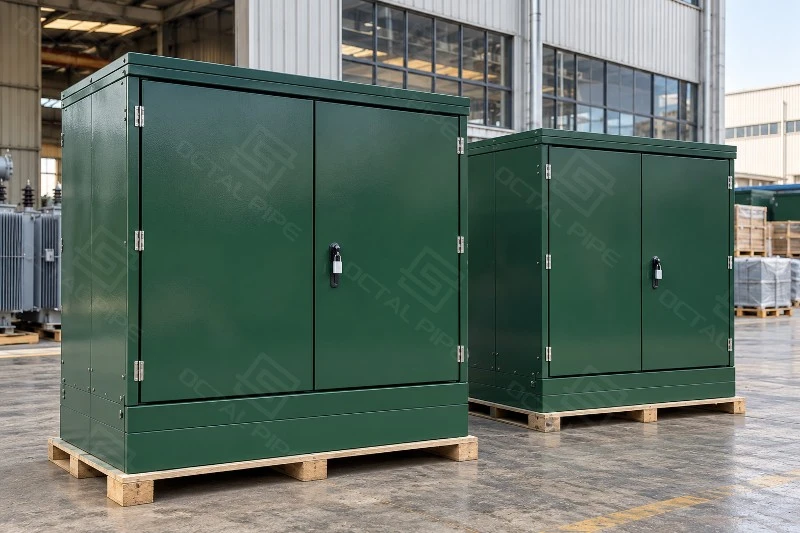
Pad mounted transformers are particularly suitable where underground medium-voltage cables feed outdoor distribution points and a compact ground-mounted transformer is preferred.
Residential distribution commonly uses smaller single-phase or three-phase units to supply groups of homes and local services. Single-phase pad-mounted transformers covered by IEEE C57.12.38 are specifically associated with underground primary supplies serving single-phase customers.
Commercial buildings and facilities may use three-phase pad-mounted transformers to supply shopping centers, office buildings, schools, hotels and other distributed loads.
Industrial installations can use larger three-phase units where medium-voltage incoming power must be reduced to the voltage required by production equipment, auxiliary systems or low-voltage distribution panels.
Renewable energy projects may also use pad-mounted transformers as part of solar or wind electrical systems, including step-up applications. The voltage ratio, cooling arrangement, insulation level and protection configuration need to match the generation equipment and grid connection requirements.
Why Choose Octal Pipe
Octal Pipe approaches pad-mounted transformer projects around the actual equipment configuration rather than treating every order as the same standard unit. Voltage ratings, capacity, winding material, tap arrangement, feed type, cabinet layout and protection components are checked together so that the electrical and mechanical details remain consistent.
The same attention is applied to documentation. Nameplate data, technical schedules, drawings, test reports and packing information need to correspond to the transformer that is actually shipped. This becomes especially useful on replacement projects, where terminal locations, cabinet dimensions, cable access and foundation details can matter just as much as the kVA rating.
Project communication is kept practical as well. If a requested configuration, accessory or document requirement does not match the transformer design, the issue can be identified before production rather than being left until inspection or installation. Previous drawings and records can also be referenced when a customer returns for repeat units, helping maintain consistency between different orders.
FAQ

01.Does a pad mounted transformer require approval from the local utility?
02.How is fuse protection coordinated in a pad mounted transformer?
03.Can a new pad mounted transformer operate in parallel with an existing transformer?
04.Can a pad mounted transformer handle bidirectional power flow from solar or battery storage systems?
05.What should be inspected when a pad mounted transformer arrives on site?
Certifications

CE Certificate

ISO 9001 Certificate

API Q1 Certificate

ABS Certificate

AP-5L Certificate

API-5CT Certificate
Hot Tags: pad mounted transformer, pad mounted distribution transformer, three phase pad mounted transformer
Previous
No InformationYou Might Also Like


Send Inquiry