





Oil Immersed Transformer
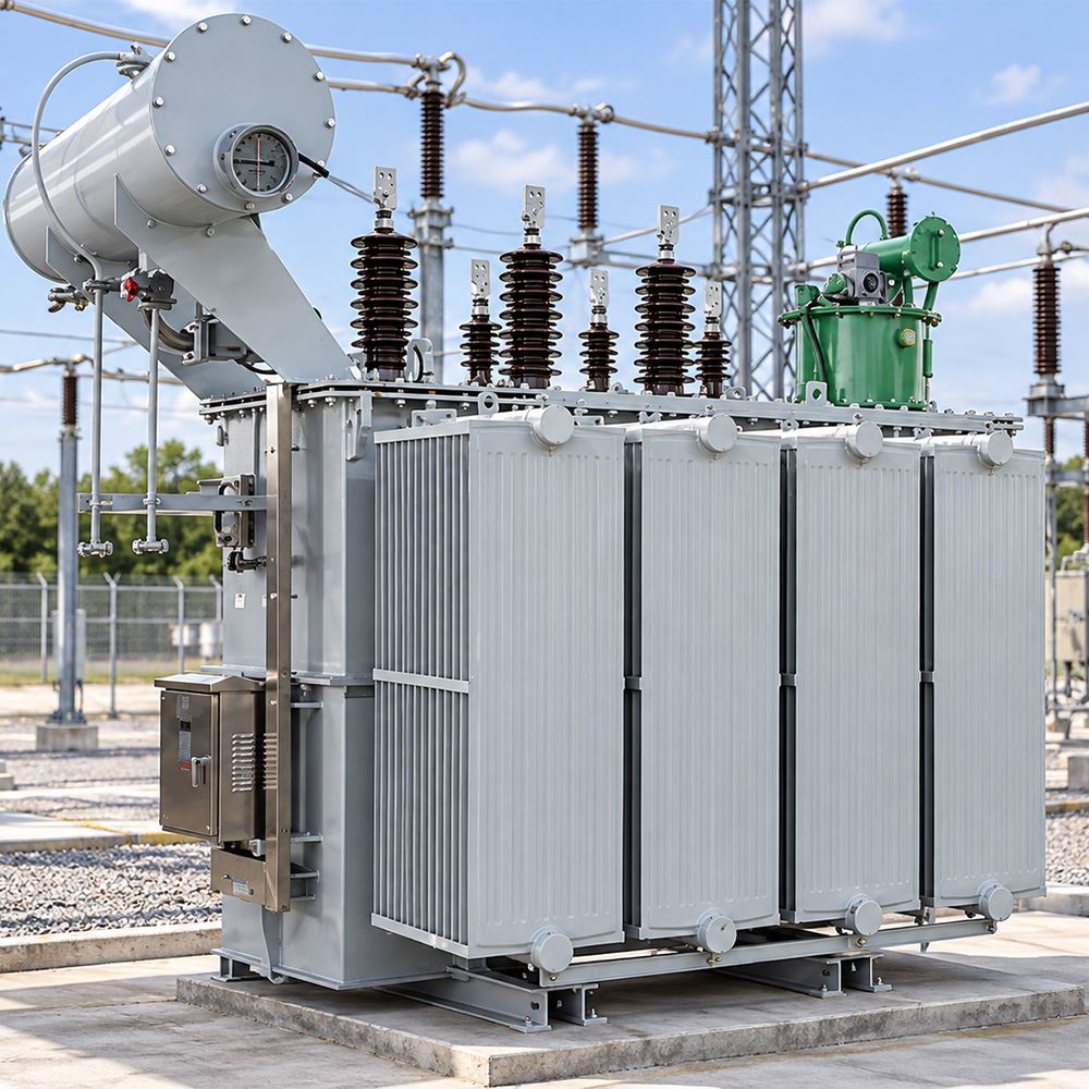
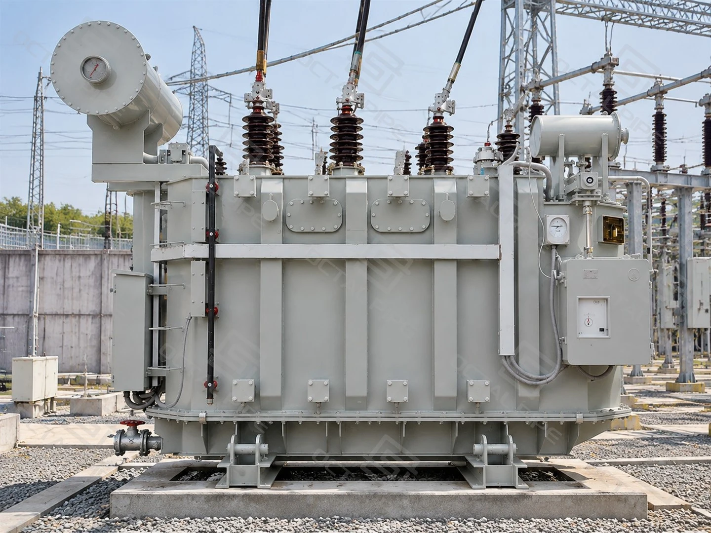
An oil immersed transformer transfers electrical power between different voltage levels while using insulating oil to provide electrical insulation and remove heat from the core and windings. In distribution systems, it is commonly used to reduce medium-voltage power to the low-voltage level required by industrial equipment, commercial facilities and local power networks.
Compared with dry-type transformers, oil immersed transformers are widely selected for outdoor installations and higher-capacity applications because the insulating oil provides both dielectric insulation and efficient heat dissipation. Depending on the project requirements, transformers can be configured for distribution or power applications with different voltage ratios, rated capacities, cooling methods and protection arrangements.
Octal Pipe provides oil immersed transformers with complete technical specifications matched to project requirements, covering transformer rating, voltage class, cooling arrangement, accessories, testing requirements and documentation. By selecting suitable configurations and coordinating supply requirements, Octal Pipe helps customers achieve a practical balance between technical requirements and project budget. The typical supply price range is USD 3,000 to 80,000 per unit (depending on rated capacity, voltage level, transformer configuration, winding material, cooling method and required technical options).
Oil Immersed Transformer Specifications
Oil immersed transformers are available in different voltage classes, capacity ranges and cooling configurations according to the power system requirements. The final design is determined by the rated capacity, voltage level, frequency, insulation system, cooling method and installation conditions.
| Parameter | Reference Configuration | Specification Requirement |
|---|---|---|
| Rated capacity | 30–2,500 kVA | Select against maximum demand, load profile and planned expansion |
| Number of phases | Three-phase | Confirm the incoming supply and connected loads |
| Primary rated voltage | 6, 6.3, 10, 10.5 or 11 kV | State the required rated voltage and system conditions |
| Secondary rated voltage | 0.4 kV | Other secondary voltages require design confirmation |
| Rated frequency | 50 Hz or 60 Hz | Specify the frequency for which the transformer will be designed |
| Vector group | Dyn11 or Yyn0 | Confirm phase displacement and neutral requirements |
| Cooling | ONAN for conventional naturally cooled designs | State the rated capacity under the specified cooling conditions |
| Oil preservation | Hermetically sealed or conservator arrangement | Confirm the tank design and associated accessories |
| Winding conductor | Copper or aluminium | Identify the conductor material in the technical offer |
| HV tapping range | ±5% or ±2×2.5% reference options | Define the tap positions and tap-changer type |
| Short-circuit impedance | Capacity- and design-specific | Specify the required value, reference conditions and tolerance |
| No-load and load losses | Model-specific guaranteed values | Record the measurement conditions and applicable tolerances |
| Insulating liquid | Mineral insulating oil for conventional designs | Specify the oil grade and applicable requirements |
| Dimensions, total mass and oil quantity | Model-specific | Confirm against the approved general arrangement drawing |
Transformer performance is defined by more than the rated capacity. Parameters such as vector group, short-circuit impedance, no-load loss, load loss and insulation level directly affect system compatibility, operating efficiency and protection coordination. These values are confirmed according to the transformer design, applicable standards and project requirements.

Hermetically Sealed and Conservator Designs
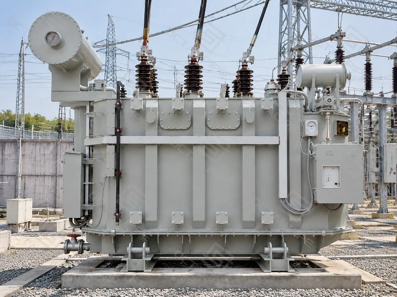
The oil preservation system controls how the transformer manages the expansion and contraction of insulating oil during operation. Different tank designs are used depending on transformer capacity, installation conditions and maintenance requirements.
| Design | Construction and Oil Expansion | Typical Application |
|---|---|---|
| Hermetically sealed | The transformer tank is sealed from direct contact with ambient air. Oil expansion is accommodated through a corrugated tank wall, flexible expansion elements or a sealed gas space. | Commonly used for compact distribution transformers where reduced oil oxidation and lower maintenance requirements are preferred. |
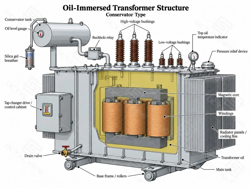
| Conservator type | A conservator tank above the main transformer tank provides additional space for oil volume changes caused by temperature variation. | Commonly used for larger transformers where oil monitoring, accessories and long-term service management are required. |
Both designs are widely used for oil immersed transformers, with the selection depending on transformer capacity, operating environment and maintenance requirements.
The accessory arrangement is related to the selected tank design. Typical transformer accessories may include oil level indicators, temperature indicators, pressure relief devices, drain and sampling valves, Buchholz relays (for applicable conservator designs), alarms and protection contacts.
The final transformer configuration is determined according to the rated capacity, voltage level, cooling method, installation conditions and project technical requirements.
Cooling and Voltage Regulation
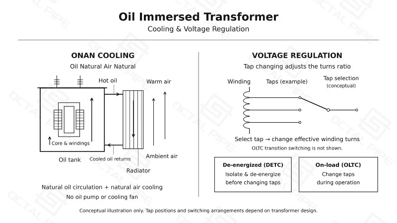
ONAN means Oil Natural Air Natural. Oil circulates by natural convection, carrying heat from the active parts to the tank or radiators, where surrounding air removes it. The cooling process does not depend on externally driven oil circulation.
The transformer's rated output must be assessed against its specified ambient conditions and cooling arrangement. Ventilation around the cooling surfaces matters, particularly where the transformer is installed inside an enclosure or building.
Voltage regulation requires a separate decision. A de-energized tap changer adjusts the winding ratio while the transformer is isolated and de-energized. An on-load tap changer is designed to change taps during operation. These arrangements have different equipment, control and maintenance requirements.
Voltage regulation is provided through a suitable tap changer configuration. A de-energized tap changer adjusts the winding ratio while the transformer is isolated and de-energized, while an on-load tap changer (OLTC) allows tap adjustment during operation. The selected tap range and operating method should match the system voltage variation requirements, and the transformer ratio and tap position are verified during factory testing.
For detailed guidance on capacity selection, transformer configuration and RFQ requirements, refer to the Oil Immersed Transformer Selection Guide (PDF)
Losses, Impedance and Thermal Performance
Transformer efficiency and operating reliability are closely related to electrical losses, impedance characteristics and thermal performance. These parameters affect energy consumption, voltage stability, fault performance and the long-term operating condition of the transformer.
| Performance Item | Description |
|---|---|
| No-load loss | Power loss generated in the transformer core when the transformer is energized without supplying load. It is mainly related to core material, magnetic flux density and core design. |
| Load loss | Power loss occurring under load conditions, mainly caused by winding resistance and additional stray losses. It varies with the operating current of the transformer. |
| Short-circuit impedance | The transformer impedance value expressed as a percentage of rated voltage and current. It affects voltage regulation, fault current characteristics and parallel operation capability. |
| Temperature rise | The increase in oil and winding temperature during operation compared with the surrounding ambient temperature. It is controlled through the transformer design and cooling system. |
| Sound level | The operating noise generated by the transformer core and electromagnetic effects, measured according to the specified test conditions. |
For continuously energized transformers, no-load loss is present throughout the operating period, making it an important factor in lifetime energy consumption. For example, a 200 W reduction in no-load loss operating for 8,760 hours per year can reduce annual energy consumption by approximately 1,752 kWh.
The thermal capability of an oil immersed transformer is determined by the cooling arrangement, insulation system and applicable temperature-rise limits. According to IEC 60076-2, liquid-immersed transformers are evaluated through temperature-rise requirements and thermal performance tests to ensure suitable operation under the specified ambient conditions.
Manufacturing and Factory Testing
Transformer manufacturing combines magnetic-core preparation, winding production, insulation processing and tank assembly. Drying and oil handling require particular attention because moisture and contamination affect the insulation system.
Core preparation and winding manufacture → Active-part assembly → Controlled drying → Tank assembly → Oil processing and filling → Factory testing → Dispatch preparation
The drying and filling procedures must suit the insulation system and tank construction. Vacuum treatment should follow the approved manufacturing procedure and the tank's pressure capability.
Factory acceptance should be based on recorded results for the supplied equipment. The inspection schedule should require routine-test reports covering 100% of completed units, identified by serial number.
| Inspection or Test | Purpose | Required Record or Acceptance Basis |
|---|---|---|
| Winding resistance | Assess winding continuity and connections | Recorded resistance, temperature and applicable tap positions |
| Voltage ratio and phase displacement | Verify the specified ratio and connection | Results against the approved vector group and tap schedule |
| No-load loss and current | Verify excitation performance | Measured values, test voltage and frequency |
| Load loss and short-circuit impedance | Verify guaranteed electrical performance | Results corrected to the agreed reference conditions |
| Applicable dielectric routine tests | Verify insulation withstand performance | Test method and levels selected under IEC 60076-3 |
| Tank tightness testing | Check the oil-containing assembly for leakage | Procedure appropriate to the tank design and recorded result |
| Accessory and control checks | Verify indications, contacts and auxiliary functions | Checks against the approved accessory and wiring schedules |
Ratio, winding-resistance and impedance measurements address different aspects of transformer condition; one successful test does not replace the others. Temperature-rise testing and other design-verification tests need a clearly agreed scope. Dielectric requirements vary with the winding and insulation category. Short-circuit withstand evidence may involve calculation, theoretical evaluation and special testing under IEC 60076-5; it should not be described as a destructive test routinely performed on every supplied unit.
Standards and Technical Documentation
Oil immersed transformers are designed and tested according to applicable international standards covering transformer performance, insulation coordination, temperature rise, short-circuit capability and insulating oil quality. The applicable standard combination depends on the transformer type, voltage class, rated capacity and project requirements.
| Standard | Application Scope |
|---|---|
| IEC 60076-1 | General requirements, ratings, service conditions and basic performance requirements for power transformers |
| IEC 60076-2 | Temperature-rise limits and thermal performance tests for liquid-immersed transformers |
| IEC 60076-3 | Insulation levels, dielectric tests and insulation coordination requirements |
| IEC 60076-5 | Short-circuit withstand capability of transformers |
| IEC 60296 | Requirements and test methods for mineral insulating oils used in electrical equipment |
For each transformer project, the technical documentation package is prepared according to the approved configuration and includes key information such as transformer rating data, voltage ratio, vector group, cooling method, loss values, impedance, insulation level and accessory arrangement.
Each transformer is identified through its serial number, nameplate information and test records, allowing the delivered unit to be traced from factory production through final installation. For projects requiring third-party inspection, inspection points and document review requirements can be coordinated according to the project quality plan.
Applications and Site Requirements
Factory distribution and production-line expansion. A transformer feeding processing machinery, pumps or workshop equipment must suit the actual demand profile and the existing electrical system. Installation space, cable entry, neutral connections and protection coordination need checking alongside capacity.
Replacement within an existing substation. A replacement unit may have the correct kVA rating while still requiring changes to the foundation, busbar connections or cable terminations. The approved drawing should confirm overall dimensions, terminal positions, mass and handling arrangements before dispatch.
Remote and exposed installations. Outdoor projects may introduce high altitude, elevated ambient temperature, salt contamination or corrosive conditions. These conditions should be stated in the enquiry so the external insulation, cooling and protective finish can be assessed. Normal service conditions commonly use an altitude limit of 1,000 m; higher sites require specific consideration rather than an assumed standard rating.
Facilities with continuous operation. Where the transformer remains energized throughout the year, loss guarantees and access for inspection deserve particular attention. Maintenance space and replacement access should be considered while the installation layout is still being developed.
Why Choose Octal Pipe
Octal Pipe supports oil immersed transformer supply by helping customers match the transformer configuration with their actual project requirements. Before supply, key parameters such as rated capacity, voltage ratio, cooling method, installation conditions and required standards are reviewed to avoid specification gaps during production and inspection.
For industrial and infrastructure projects, transformer supply often involves more than the main equipment. Octal Pipe coordinates related technical information, including datasheets, drawings, test reports, nameplate details and shipment documents, so that the delivered transformer can be checked against the approved project requirements.
Many transformer projects are integrated into existing power systems, where small differences in terminal arrangement, accessories or documentation can affect installation and commissioning. Maintaining clear technical communication from specification review to final delivery helps reduce these risks and supports smoother project execution.
FAQ

01.Can oil immersed transformers operate in parallel?
02.Can a 50 Hz transformer be used on a 60 Hz supply?
03.Can an oil filled transformer be installed indoors?
04.Does a hermetically sealed transformer require maintenance?
05.What is the service life of an oil immersed transformer?
Certifications

CE Certificate

ISO 9001 Certificate

API Q1 Certificate

ABS Certificate

AP-5L Certificate

API-5CT Certificate
Hot Tags: oil immersed transformer, China oil immersed transformer manufacturers, suppliers, factory
Previous
No InformationYou Might Also Like



Send Inquiry