




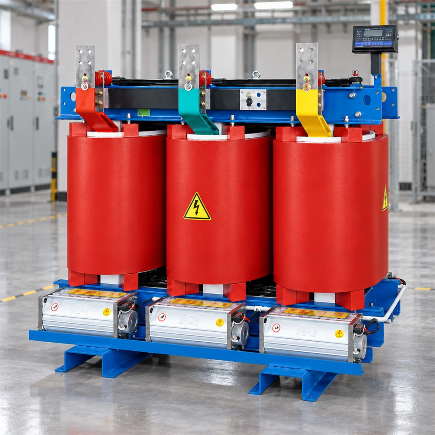

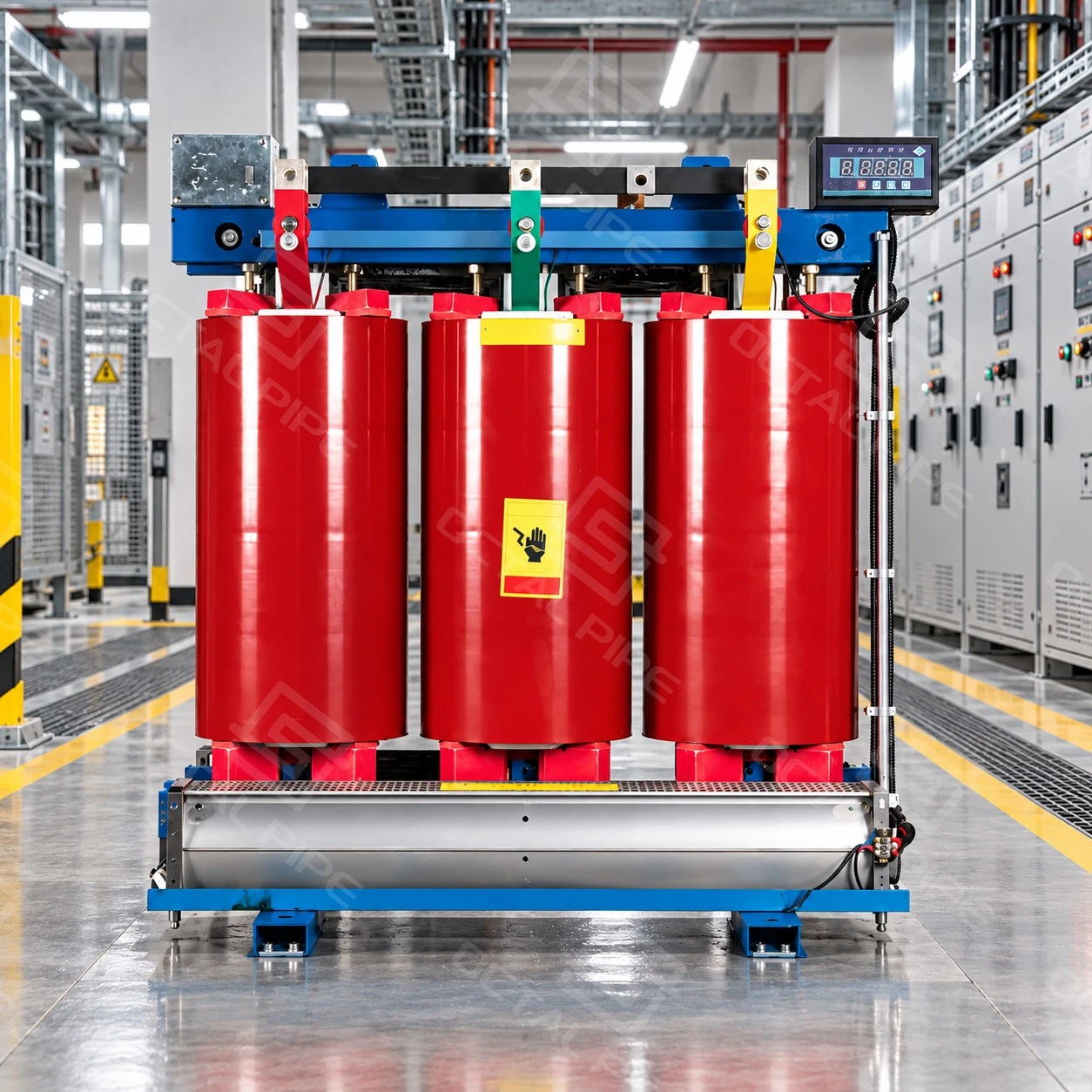
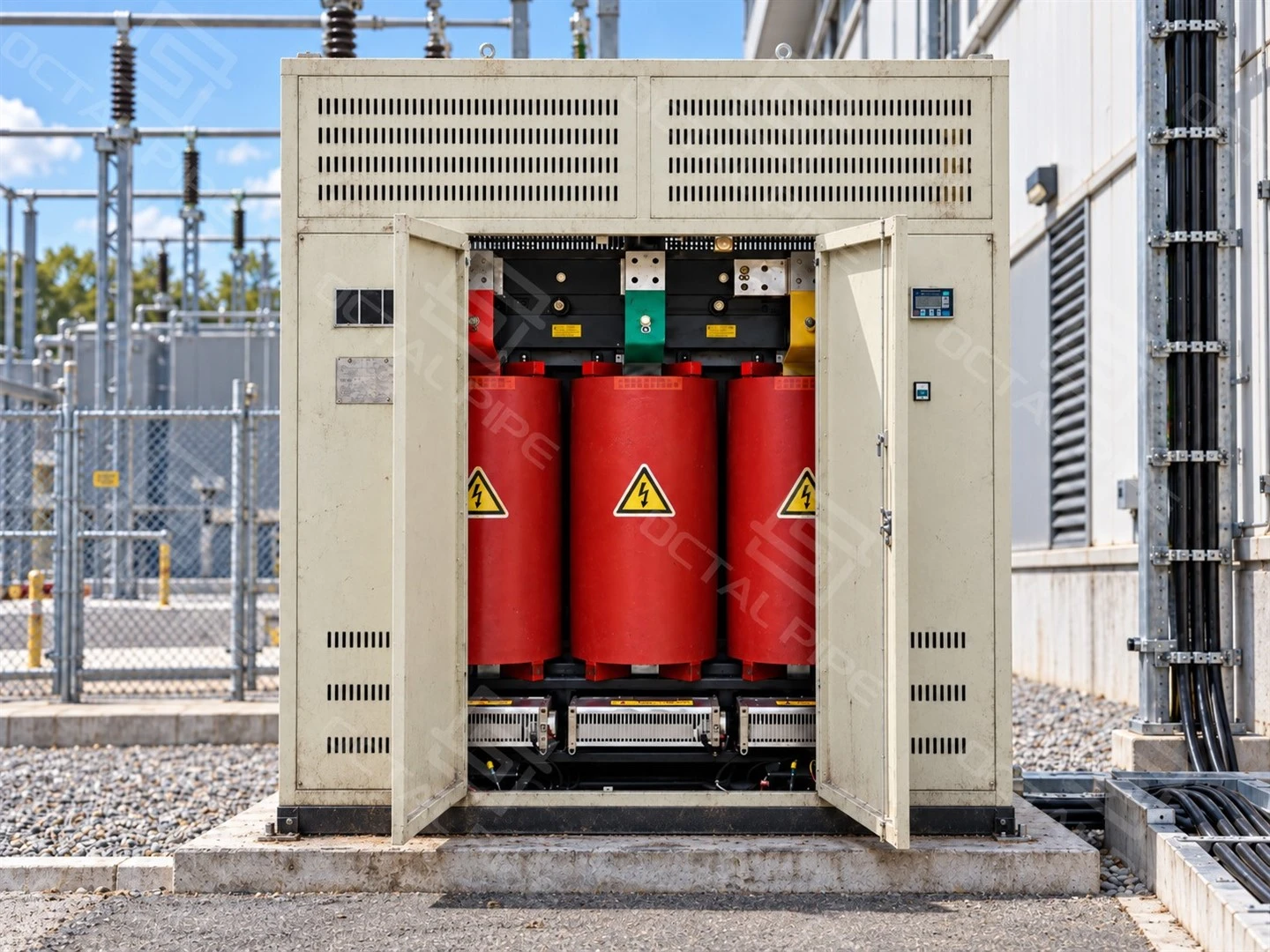
Dry Type Transformer
Primary Voltage: 6 kV, 6.3 kV, 6.6 kV, 10 kV, 11 kV; other voltages subject to design confirmation
Secondary Voltage: 0.4 kV; other ratings on request
Frequency: 50 Hz or 60 Hz, as specified
Phase: Three-phase
Cooling Type: AN; AF where designed and specified
Insulation Construction: Cast resin or vacuum pressure impregnated (VPI)
Insulation Thermal Class: Class F or Class H, depending on design
Winding Material: Copper or aluminium
Enclosure: IP00 active part or a specified protective enclosure
Standards: IEC 60076-11 and other applicable IEC 60076 requirements
Tap Adjustment: De-energized taps; range and positions as specified
A dry type transformer transfers electrical power between voltage levels without immersing its core and windings in insulating liquid. Solid insulation and air provide the dielectric system, while heat passes from the active parts to the surrounding air. In medium-voltage distribution, dry-type units supply factory equipment, commercial buildings and facilities where the location of the transformer and the management of insulating oil influence equipment selection.
A suitable transformer must match both the electrical load and the installation environment. Rated capacity and voltage ratio establish the basic duty; insulation construction, temperature rise, cooling, enclosure and partial-discharge performance determine whether the proposed configuration can operate under the specified conditions.
Octal Pipe supplies dry type transformers for industrial and commercial power distribution projects, with electrical ratings, cooling arrangements, enclosures, accessories and testing requirements matched to each application. For conventional small and medium distribution transformers, the indicative price range is USD 3,000–35,000 per unit (subject to rated capacity, voltage level, winding material, loss requirements and enclosure configuration). Larger or specially engineered units are quoted individually according to their technical specifications.
Dry Type Transformer Specifications
Dry type transformers are available in cast resin and vacuum pressure impregnated (VPI) constructions, using solid insulation and air cooling instead of an oil-filled tank. Three-phase distribution models commonly cover 100–2,500 kVA, with different voltage ratings, winding materials, cooling arrangements and enclosure options for industrial and commercial power distribution.
| Parameter | Reference Configuration | Information to Confirm |
|---|---|---|
| Rated capacity | 100–2,500 kVA reference range | Maximum demand, load profile and planned expansion |
| Transformer construction | Cast resin; VPI construction where specified | Required insulation system and installation conditions |
| Number of phases | Three-phase | Incoming supply and connected load arrangement |
| Primary rated voltage | 6, 6.3, 6.6, 10 or 11 kV; higher-voltage designs available | Exact winding voltage and insulation requirements |
| Secondary rated voltage | 0.4 kV reference configuration | Required output voltage; other ratings are design-specific |
| Rated frequency | 50 Hz or 60 Hz | Frequency for which the unit will be designed |
| Vector group | Dyn11 or Yyn0 reference options | Phase displacement, neutral and system compatibility |
| Winding conductor | Copper or aluminium | Conductor material and guaranteed performance |
| Cooling | AN; AF where designed and specified | Natural-air rating and any additional forced-air rating |
| Insulation thermal class | Class F or Class H, depending on design | Complete insulation-system classification |
| Average winding temperature rise | Design-specific; common limits shown below | Specified rise under the applicable service conditions |
| HV tapping | De-energized taps; ±2×2.5% is a common configuration | Tap positions, range and operating procedure |
| Short-circuit impedance | Capacity- and design-specific | Guaranteed value, reference conditions and tolerance |
| No-load and load losses | Model-specific guaranteed values | Measurement conditions, reference temperature and tolerances |
| Enclosure | IP00 active part or a specified enclosure | Protection degree, ventilation and installation suitability |
| Dimensions and total mass | Model-specific | Approved drawing, handling route and foundation requirements |
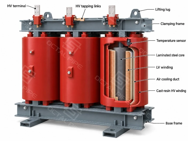
In cast resin transformers, the medium-voltage windings are typically encapsulated in epoxy resin, while the low-voltage windings may use a different insulation construction. VPI transformers use resin-impregnated winding insulation without fully encapsulating the coils in cast resin. Both constructions are available with copper or aluminum conductors, and their winding insulation, ventilation arrangements and temperature-rise characteristics are reflected in the final transformer design.

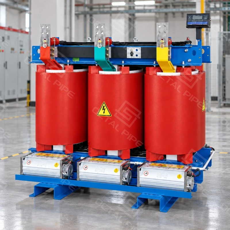
For a consolidated reference of dry type transformer ratings, configuration and technical data, see the Dry Type Transformer Technical Data (PDF).
Dry Type Transformer Standards
IEC 60076-11 defines the principal requirements and tests for medium-voltage dry type transformers. Its scope includes equipment with a highest voltage for equipment (Um) up to 72.5 kV and at least one winding operating above 1.1 kV, with exclusions for certain small and special-purpose designs.
| Standard | Main Coverage |
|---|---|
| IEC 60076-11 | Dry type transformer service conditions, temperature-rise limits, insulation requirements and testing. |
| IEC 60076-1 | General requirements for transformer ratings, connections, tolerances and marking, where referenced by the product standard. |
| IEC 60076-3 | Insulation levels, dielectric tests and external air clearances, where applicable. |
| IEC 60076-5 | Thermal and dynamic withstand under external short-circuit conditions. |
| IEC 60076-12 | Loading guidance and assessment of insulation ageing in relation to temperature, time and load. |
| IEC 60085 | Thermal evaluation and classification of electrical insulation materials and systems. |
| IEC 60529 | Enclosure IP ratings covering access to hazardous parts, solid objects and water ingress. |
The technical specification identifies the applicable standard editions, guaranteed losses and project-specific efficiency requirements. Approved drawings define dimensions, terminal positions and accessories, while test reports document measured performance against the specified requirements. Installation and maintenance instructions cover the supplied configuration, including cooling arrangements, electrical connections and service access.
Cast Resin and VPI Insulation
Dry type transformers are commonly manufactured with cast resin or vacuum pressure impregnated (VPI) winding insulation. The two constructions use different resin application and curing processes, resulting in differences in winding protection, surface insulation and exposure to the surrounding environment.
|
Construction |
Insulation Process |
Technical Characteristics |
|---|---|---|
|
Cast Resin Transformer |
Medium-voltage windings are typically encapsulated in epoxy resin using vacuum casting, followed by controlled curing. |
The solid resin enclosure protects the winding surfaces from dust and moisture exposure. Casting quality, resin integrity and partial discharge performance are important characteristics of the insulation system. |
|
VPI Transformer |
Winding insulation is impregnated with insulating varnish or resin under vacuum and pressure, then cured in a controlled heating process. |
Resin penetrates the winding insulation without forming the same thick, rigid encapsulation as cast resin. The winding assembly remains more open to circulating cooling air and the installation environment. |
The manufacturing process has a direct effect on insulation quality. In cast resin transformers, inadequate drying, trapped air or defects formed during casting can create voids within the resin, potentially affecting dielectric performance and partial discharge levels. Vacuum casting and controlled curing help limit these defects.
For VPI transformers, the quality of resin penetration and curing affects the electrical insulation and mechanical stability of the windings. Because the coils are not fully encapsulated, ventilation, dust accumulation and moisture exposure receive particular attention in the enclosure and installation design.
Both constructions are used in industrial power distribution, including factory substations, electrical rooms and commercial installations. A cast-resin winding provides additional surface protection, but the transformer still requires suitable ventilation and environmental protection.
Cooling, Temperature Rise and Thermal Protection
Dry type transformers release heat from the core and windings into the surrounding air. Air Natural (AN) cooling relies on air circulating through the winding cooling passages. Air Forced (AF) cooling adds fans to increase airflow and heat removal. On designs with an additional AF rating, this can support higher loads within the manufacturer's specified operating limits. The permitted increase and duration depend on the transformer design.
For indoor installations, cooling also depends on how effectively the electrical room removes this heat. Restricted ventilation raises the temperature of the air entering the transformer, causing the windings to run hotter at the same load. Room ventilation therefore forms part of the cooling arrangement, alongside the transformer's own air passages and fans.
Insulation Class and Temperature Rise
Insulation thermal class describes the temperature capability of the winding insulation system. Winding temperature rise measures the increase in average winding temperature above the surrounding cooling air. For dry type transformers designed to IEC 60076-11, the following limits apply under normal service conditions:
| Insulation Class | Insulation System Thermal Classification | Average Winding Temperature-Rise Limit |
|---|---|---|
| Class F | 155°C | 100 K |
| Class H | 180°C | 125 K |
The average temperature does not represent the hottest point within a winding. Local hot spots are assessed separately against the insulation system's thermal limits, which is why both insulation class and temperature rise appear in transformer specifications.
Temperature Monitoring and Protection
Winding temperature sensors allow a controller to display operating temperatures and respond as heat builds up. In a system equipped with fan control, alarm and trip outputs, the controller starts the fans at the selected threshold, signals an alarm if the temperature continues to rise, and provides a trip contact to the circuit-breaker control circuit at the shutdown threshold. These settings are matched to the transformer's thermal design and sensing arrangement.
Partial Discharge and Insulation Quality
Partial discharge (PD) is a localized electrical discharge within or along an insulation system that does not bridge the entire insulation between conductors. Repeated discharge can gradually erode the insulation and develop into a more serious electrical failure.
For three-phase dry type transformers, IEC 60076-11:2018 specifies a routine test that measures discharge activity after a brief period of elevated electrical stress.
| Test Stage | Requirement |
|---|---|
| Pre-stress voltage | 1.8 × rated voltage for 30 seconds |
| PD measurement voltage | Reduce without interruption to 1.3 × rated voltage for 3 minutes |
| Acceptance limit | Apparent charge ≤10 pC during the measurement period |
The voltage multiples refer to the rated phase-to-phase voltage. Results are recorded in picocoulombs, together with the applied voltage and test conditions.
The factory report links these measurements to the tested transformer. PD testing can reveal insulation weaknesses that are not visible during an external inspection, allowing affected windings to be investigated before the transformer enters service.
Enclosure and Installation Conditions
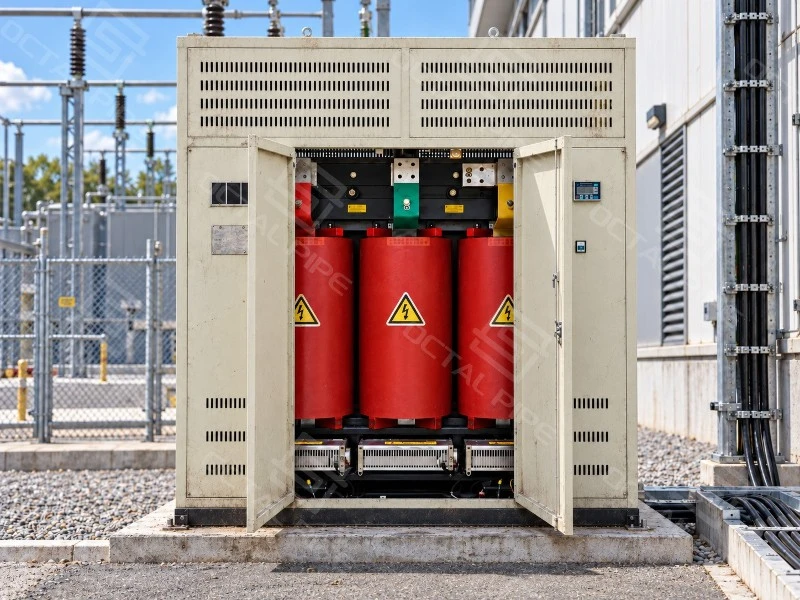
Dry type transformers are available as IP00 open units or with a protective enclosure. Open units leave the active parts exposed and are typically installed in dedicated electrical rooms with restricted access. An enclosure provides a barrier around the transformer, with its IP rating identifying the degree of protection against access to hazardous parts, solid objects and water ingress.
The enclosure also forms part of the cooling arrangement. Ventilation openings allow cooler air to enter and heated air to escape; restricted airflow can increase winding temperatures and limit the available output. Outdoor installations add exposure to rain, condensation and corrosion, so their enclosure construction and environmental protection differ from those of a standard indoor assembly.
Common reference conditions for distribution designs are a maximum ambient air temperature of 40°C and an installation altitude up to 1,000 m. Higher ambient temperatures leave less margin for heat dissipation, while the lower air density at higher elevations reduces cooling effectiveness. Depending on the design, operation beyond these conditions may involve a lower permissible load or changes to the cooling and insulation arrangements.
Climatic, Environmental and Fire Behaviour Classes
Low temperatures during transport, condensation on winding surfaces and airborne contamination place different demands on transformer insulation. IEC 60076-11:2018 defines climatic, environmental and fire behaviour classes to describe performance under these conditions.
| Classification | Conditions Covered |
|---|---|
| C2 - Climatic | Minimum ambient temperature of −25°C during operation, transport and storage. |
| C3 - Climatic | Operation down to −25°C, with transport and storage down to −40°C. |
| E2 - Environmental | Frequent condensation, light pollution, or a combination of both. |
| E3 - Environmental | Frequent condensation, moderate pollution, or a combination of both. |
| E4 - Environmental | Frequent condensation, heavy pollution, or a combination of both. |
| F1 - Fire behaviour | Restricted flammability, with requirements to minimize toxic emissions and opaque smoke. |
F1 fire behaviour and Class F insulation describe different properties. Class F identifies a 155°C insulation thermal class, while F1 addresses the transformer's behaviour when exposed to fire under the specified test conditions.
Losses and Operating Performance
No-load loss continues whenever the transformer is energized, including periods when connected equipment is switched off. Load loss increases with winding current and contributes more heavily to energy consumption as demand rises. Annual energy losses therefore depend on both the energized hours and the load carried throughout the day.
A transformer with 200 W lower no-load loss uses 1,752 kWh less energy per year when energized for 8,760 hours. This saving applies to the no-load component alone; differences in load loss also affect total annual consumption.
Load-loss figures are quoted at a specified reference temperature. A figure stated at 120°C, for example, expresses the loss corrected to that winding temperature. The permissible winding temperature rise above ambient is a separate rating, expressed in kelvins (K).
Copper and aluminium windings can both meet specified loss and temperature-rise requirements. Their different electrical properties affect conductor sizing and winding dimensions, while the cooling arrangement governs heat removal. The finished design determines the transformer's performance, so conductor material alone does not establish its efficiency.
Manufacturing Process
Cast-resin and vacuum-pressure impregnated (VPI) transformers follow different winding-insulation processes. Both begin with winding manufacture and drying, followed by resin processing and controlled curing.
Cast-resin coils:
Winding → Drying → Mould preparation → Vacuum casting → Controlled curing → Demoulding
VPI coils:
Winding → Drying → Vacuum-pressure impregnation → Controlled curing
The finished coils are assembled with the core and secured by the supporting and clamping structures. Terminal connections, temperature sensors and specified fans or enclosures are then fitted before final inspection and electrical testing.
Factory Testing and Inspection
Routine electrical tests verify each transformer's voltage ratio, losses and insulation performance. Test records identify the unit by serial number and include the measurement conditions, allowing the results to be traced to the delivered equipment.
| Inspection or Test | Recorded Results and Checks |
|---|---|
| Winding resistance | Resistance values, winding temperature and applicable tap positions. |
| Voltage ratio and phase displacement | Measured ratios at the specified taps and verification of the vector group. |
| No-load loss and current | Measured values at the specified voltage and frequency. |
| Load loss and short-circuit impedance | Results corrected to the specified reference temperature. |
| Dielectric tests | Applied test voltages, test duration and insulation withstand results. |
| Partial-discharge measurement | Apparent charge in pC, applied voltage and test sequence. |
| Thermal protection and fan controls | Sensor response, alarm and trip outputs, and fan operation where fitted. |
| Mechanical and enclosure inspection | Winding supports, terminals, earthing, nameplate and conformity with assembly drawings. |
Temperature-rise testing and specified climatic, environmental and fire-behaviour tests provide evidence for the relevant design. Their reports establish the tested construction and the scope of applicability.
Short-circuit withstand is verified separately under IEC 60076-5. Thermal calculations establish whether winding temperatures remain within the applicable limits at the specified fault current and duration. Dynamic withstand is demonstrated by a special short-circuit test or an agreed design review covering force and stress calculations, winding supports, clamping and manufacturing details. Test acceptance includes inspection for damage, repeat dielectric tests and other applicable routine tests, and confirmation that changes in short-circuit reactance remain within the permitted limits.
Applications and Project Integration
Indoor distribution close to the load. In commercial and industrial buildings, locating the transformer near the low-voltage distribution system can simplify the electrical layout. The room must still provide controlled access, ventilation, maintenance space and compliance with the applicable installation requirements.
Production-facility expansion. Additional machinery changes the demand profile and may introduce frequent motor starts or extended high-load periods. Capacity selection should account for the operating duty, while the cooling arrangement and room heat-removal capability need checking against the proposed load.
Replacement in an existing electrical room. The same kVA rating does not ensure a direct replacement. Terminal positions, phase arrangement, cable bending space, enclosure dimensions, mass and the handling route can affect installation. These interfaces should be checked before the transformer is manufactured.
Where oil management and installation location remain open design choices, compare the proposed dry-type arrangement with an oil immersed transformer using the same electrical duty and site requirements.
Why Choose Octal Pipe
Octal Pipe coordinates transformer specifications, inspection requirements and export delivery within the same order. We review the electrical ratings alongside the installation drawings, paying attention to terminal positions, cable connections and available space. These details are carried through into the agreed configuration, helping reduce connection and layout changes during installation.
Our team follows up on inspection records, technical drawings and shipment documents, checking that they correspond to the equipment being supplied. Packing and shipping arrangements are coordinated with the delivery schedule, with progress updates as the order moves forward. After delivery, we remain available to clarify documents and follow up on reported product issues.
FAQ

01.How do I determine the required dry type transformer capacity?
02.Can a dry type transformer supply UPS systems and variable-frequency drives?
03.Does an SCB model designation confirm energy-efficiency compliance?
04.Can dry type transformers operate in parallel?
05.Which spare parts should be included in a transformer enquiry?
Certifications

CE Certificate

ISO 9001 Certificate

API Q1 Certificate

ABS Certificate

AP-5L Certificate

API-5CT Certificate
Hot Tags: dry type transformer, dry type distribution transformer, cast resin dry type transformer, VPI dry type transformer
Previous
No InformationYou Might Also Like



Send Inquiry