


Anode Installation
Standards: DNVGL-RP-F103, DNV-RP-B401, ISO 15589-2, NACE SP0169
Anode Types:Sacrificial (Zn, Al, Mg alloys),ICCP (MMO, graphite, silicon-iron)
Installation Methods:Welded or strapped directly on pipe,Embedded in Concrete Weight Coating (CWC),Clamp or saddle mounted,Underwater installation by divers/ROVs,Powered ICCP rod systems with rectifiers
Technical Advantages:Service life: 20–40 years,Optimized current distribution, uniform CP coverage,Safe for hazardous/offshore environments,Proven performance in submarine & swamp pipelines
Applications: Offshore pipelines, risers, J-tubes, river crossings, buried pipelines
Anode installation is the work of attaching sacrificial anodes to a pipeline-by welding, clamping/strapping, or embedding them in the CWC layer-so the anodes corrode first and the steel pipe stays protected as part of the cathodic protection (CP) system. For CWC coated pipe, it also includes controlling anode position, fixing method, and cable protection so the anodes remain electrically effective without being damaged during handling, lay, or field welding.
Two main systems are applied:
- Sacrificial anodes (Zn, Al, Mg): Simple, maintenance-free, ideal for shallow water and soils.
- Impressed Current Anodes (MMO, Si-iron): Powered by rectifiers, adjustable, suited for deepwater and long-distance pipelines.
Octal Pipe designs and installs anode systems strictly per DNVGL-RP-F103, ISO 15589-2, and NACE standards, offering optimized spacing, bonding, and installation methods (welded, clamped, or CWC embedded).


Anode Installation Standards & Anode Type Selection (CP Compliance)
| Anode installation item | What it covers | Typical choice / note | Reference standards & guides |
|---|---|---|---|
| Anode installation compliance | CP system design basis for submerged/underground pipelines; acceptance framework for installation and commissioning | Used to align anode layout, attachment method, and turnover documents for offshore/subsea/buried lines | DNVGL-RP-F103 (submarine CP by galvanic anodes); DNV-RP-B401 (subsea CP practice); ISO 15589-2 (CP for petroleum & natural gas pipeline systems); NACE SP0169 / SP0177 (external corrosion control for underground/submerged piping) |
| Anode installation type: Sacrificial (galvanic) | No external power; anode material corrodes to protect the pipe | Zinc / aluminum / magnesium alloys; common for shallow water, swamp, and soil conditions where simple, distributed protection is preferred | Typically applied under the CP design basis above (project spec selects material and spacing) |
| Anode installation type: ICCP | Powered CP with adjustable output via rectifiers | MMO / graphite / silicon-iron anodes; often used for deepwater or long-distance pipelines where current demand and control are higher | Typically applied under the CP design basis above (project spec defines power/control and monitoring requirements) |
cWC Pipe Installation Methods

According to DNVGL-RP-F103, proper installation of anodes is critical for ensuring uniform current distribution and long-term effectiveness. Octal Pipe offers multiple installation solutions depending on pipeline design and environment:
1. Welded attachment (pads / bracelets)
Location control: Anodes are positioned to avoid field joints, supports, and areas that clash with stingers, rollers, or tensioner contact.
Weld + coating repair discipline: Weld areas are defined, then coating is repaired and sealed to prevent "small burn, big corrosion cell."
Cable protection: Routing is secured and protected so it doesn't snag during handling and lowering.
2. Clamp/strap mounting (anode installation kit)
Kit scope clarity: A typical anode installation kit includes clamp/saddle body, straps/fasteners, insulation pads, continuity cable, and sealing materials-so the contractor is not improvising at site.
Contact quality: Fit surfaces are controlled to avoid high-resistance contact that passes visually but fails electrically later.
Anti-loosening and transport handling: Strapping is specified so it survives trucking, lifting, and lay tension without shifting.
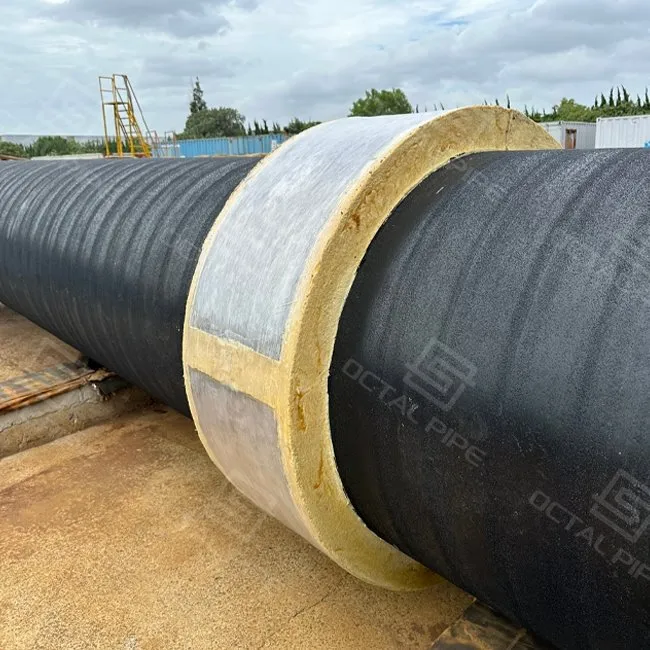
3. Embedded in CWC (for protected CP on concrete weight coated pipe)
Embed geometry: Recess/cover is controlled so the anode is protected from impact and drag while still electrically effective.
Cable exits and sealing: Cable exit points are protected and sealed so they don't become snag points or water paths.
End transitions: The CWC/anode zone is coordinated with welding cutbacks so field joint coating can be executed cleanly (when specified).
Underwater Installation:
For submarine pipelines, anodes are installed offshore by divers or remotely operated vehicles (ROVs).
Specialized clamps and welding systems are used to guarantee safe and precise placement.
DNVGL-RP-F103 specifies spacing and attachment methods to ensure even CP coverage.
Powered Anode Rod Installation (ICCP):
Anode rods (MMO, titanium-based) are placed along the pipeline route.
Connected to transformer-rectifiers onshore or topside platforms.
Provides adjustable current, suited for deepwater pipelines with high CP demand.
anode installation procedure
Use this as the anode installation procedure baseline and tighten it in your ITP where needed:
Pre-job confirmation: Confirm coating system, CWC build-up (if applicable), anode spacing plan, and "no-go" zones near field joints/supports.
- Marking & fit-up: Mark locations per drawing; verify clearance to lay equipment and handling points.
- Attachment: Install by welded or clamp/strap method; secure cable routing and strain relief.
- Continuity check: Perform electrical continuity/resistance checks and record results when specified in PO/ITP.
- Seal & repair: Repair/patch local coating damage, seal cable exits, and re-check repaired areas when specified.
- As-built documentation: Update anode IDs/locations and test records for commissioning and future CP monitoring.
Technical Advantages

Octal Pipe's anode installation solutions deliver robust corrosion control with multiple technical benefits:
Extended Service Life:
DNVGL-RP-F103 design ensures proper anode weight, spacing, and capacity, enabling 20–40 years of effective cathodic protection.
Optimized Current Distribution:
Engineering design ensures uniform polarization of the pipeline surface.
Prevents localized underprotection or overprotection, both of which can cause coating disbondment.
Safety in Hazardous Environments:
Sacrificial systems require no power, eliminating spark risks in flammable zones.
ICCP systems are designed with automatic monitoring and current control to ensure safe operation.
Integration with Coatings & CWC:
Works in tandem with FBE, 3LPE, 3LPP, and CWC coatings, providing both corrosion and buoyancy stability.
Ensures coating integrity while supplementing CP with redundancy.
Adaptability:
Sacrificial CP – Simple, low-maintenance, ideal for shallow/submerged environments.
ICCP – Adjustable, suitable for deepwater and long-distance export pipelines.
Proven Offshore Performance:
Applied in submarine pipelines, risers, and J-tubes, meeting DNV offshore design safety margins.
Anode Installation On CWC Coated Pipe (Clearance, Damage, And Cable Protection)
On a CWC coated pipe line, anode installation is not only about CP current output. The practical risk is that anodes and cables become snag/impact points during pull-in, yard lifting, roller contact, and lay operations-then the project pays for repairs and re-checks. This section focuses on anode installation on pipe in a way that stays electrically effective and constructible through CWC handling and field welding.
| Field problem seen on CWC lines | Anode installation control used on CWC coated pipe | What the buyer can request / file (when specified) |
|---|---|---|
| Anode body hits rollers/stingers or becomes a snag point during pull-in / lay | Define "no-contact zones" and required clearance to tensioners/rollers; select attachment route (welded / clamp / embedded) based on handling method | Layout drawing with no-go zones; attachment method statement; as-built anode location list |
| Cable damage from dragging, lifting slings, or pipe-to-pipe contact in stacking | Cable routing with strain relief, protected runs, and sealed exits; avoid exposed loose loops | Cable routing detail + sealing method; visual checklist; repair/re-test log (if any) |
| Concrete edge spalling around attachment area after transport | Control contact surfaces, avoid loading anode seats on fragile edges; specify handling points/stacking rules so anode zones don't take impact | Handling/packing notes; yard photos on request; damage acceptance criteria if stated in PO/ITP |
| Coating damage at welded pads / clamp contact points creates local corrosion cells | Define surface prep and coating repair steps around attachment areas; verify repaired areas (when required) | Coating repair record; holiday test/re-check record (when specified) |
| Electrical discontinuity discovered late (after lay or before commissioning) | Require continuity/resistance checks at agreed stages and capture results | Continuity/resistance test record: method + acceptance basis + results (when specified) |
Anode Spacing & Layout Rules (Avoid Field Joint Conflicts)
Most anode installation rework happens because spacing rules were written as "X meters typical" without considering field joints, CWC cutbacks, and lay equipment contact. The rules below help keep the layout buildable on CWC coated pipe while preserving the CP design intent.
| Layout rule | Why it matters on CWC coated pipe | How to state it on the PO / drawings |
|---|---|---|
| Keep anodes out of field joint coating zones | Field joints need clean access for welding, NDT, and field joint coating; anodes nearby create clearance and coating conflict | No anodes within - mm/m of field joint / girth weld zones(distance per project design) |
| Keep anodes away from concrete-free ends / end transitions | CWC ends are the highest handling and repair zone; bad placement increases spalling and slows fit-up | No anode attachment in CWC transition and concrete-free end length (state cutback length per spec) |
| Define roller/tensioner contact zones as "no-go" | Rollers/stingers can crush cables or impact anode bodies during pull-in/lay | No anodes in equipment contact bands(identified by lay method) |
| Avoid supports, bends, and high-stress handling points | Clamps, slings, and supports often land near bends/support points; anodes there get hit first | No anode installation at supports/bends/handling lift points(per drawing) |
| Treat spacing as "design intent + constructability check" | CP spacing must satisfy design, but final placement must survive construction | Spacing per CP design; final layout to be verified against field joint map and handling plan before coating/dispatch |
FAQ

Q 1 - How do you prevent electrical issues when anodes are installed on concrete weight coated pipes?
Q 2 - What should an anode installation procedure include?
Q 3 - What documents should come with anode installation (for receiving and turnover)?
Certifications

CE Certificate

ISO 9001 Certificate

API Q1 Certificate

ABS Certificate

AP-5L Certificate

API-5CT Certificate
Standards: DNVGL-RP-F103, DNV-RP-B401, ISO 15589-2, NACE SP0169
Anode Types: Sacrificial (Zn, Al, Mg), ICCP (MMO, graphite, silicon-iron)
Installation Methods: Welded, strapped, CWC embedded, clamp, underwater, ICCP rods
Applications: Offshore pipelines, submarine pipelines, swamps, buried pipelines
Service Life: 20–40 years
Hot Tags: CWC anode installation, China CWC anode installation manufacturers, suppliers, factory
Next
No InformationYou Might Also Like


Send Inquiry