Drill pipe connects the drilling rig's surface drive system to the bottomhole assembly. During rotary drilling, it transmits torque, carries tensile loads and delivers drilling fluid to the bit. As the well deepens, additional joints are connected to extend the drill string; during a trip, those connections are broken out so the string can be withdrawn.
The key features of drill pipe come from its construction: a heat-treated steel body, thickened pipe ends, welded tool joints and a continuous internal flow passage. Each part has a different role in handling the loads and repeated connections encountered during drilling.
Heat-Treated Steel for Drilling Loads
The pipe body is typically made from seamless steel tubing, with heat treatment used to achieve the specified strength and mechanical properties. Common drill pipe grades include E75, X95, G105 and S135.
| Common drill pipe grade | Minimum pipe-body yield strength |
|---|---|
| E75 | 75,000 psi |
| X95 | 95,000 psi |
| G105 | 105,000 psi |
| S135 | 135,000 psi |
The strength values for API 5DP drill pipe grades describe pipe-body yield strength, rather than the working load of the complete assembly. Selection also depends on wall thickness, anticipated tension and torque, connection capacity and operating conditions. A higher grade alone does not establish suitability for a drilling program.


Upset Ends and Friction-Welded Tool Joints
The pipe-body ends are heated and upset by forging, forming a thicker section for attachment to the tool joints. Depending on the design, the wall is thickened internally, externally or in both directions, producing IU, EU or IEU ends. The transition profile matters because it affects how bending and tensile loads pass between sections of different thickness.
Separately manufactured pin and box tool joints are attached to these ends by friction welding, followed by controlled weld-zone heat treatment. Alignment between the pipe body and tool joint is maintained during welding, while subsequent hardness checks and nondestructive examination verify the weld-zone condition before final acceptance.


Bending Fatigue in Directional Drilling
When drill pipe rotates through a curved wellbore, it experiences repeated bending stresses. In a simplified rotating-bending model, each complete revolution produces one bending stress cycle at a given point on the pipe. These cycles can initiate cracks where upset transitions, corrosion pits or handling damage concentrate stress.
The number of cycles accumulates quickly, even over a relatively short operating period:
| Illustrative rotational speed | Bending cycles in 1 hour | Bending cycles in 10 hours |
|---|---|---|
| 60 rpm | 3,600 | 36,000 |
| 100 rpm | 6,000 | 60,000 |
| 120 rpm | 7,200 | 72,000 |
Calculated as rpm × 60 × rotating hours, assuming continuous rotation through a steady bend.
At 100 rpm, a pipe section exposed to the bend for 10 hours undergoes approximately 60,000 bending cycles. The damage associated with those cycles depends on bending stress, axial tension, local geometry and corrosion conditions. Cycle count therefore needs to be considered together with wellbore curvature and pipe condition when assessing continued service.

A Continuous Passage for Drilling Fluid
Drilling mud flows through the pipe body, upset sections and tool-joint bores before reaching the bottomhole assembly and bit nozzles. After leaving the bit, it returns through the annulus between the drill string and the wellbore or casing, carrying rock cuttings toward the surface and helping cool and clean the cutting area.
The bore is not necessarily the same diameter throughout a finished drill pipe joint. A tool joint may have a smaller internal diameter than the pipe body. Mud accelerates through this narrower section and expands again downstream, creating additional pressure loss. Although the loss at one connection may be small, it is repeated at every similar connection along the string.
In a long horizontal section, these repeated restrictions can consume a meaningful share of the available pump pressure. Assessing drill pipe ID and pressure loss therefore requires the actual pipe-body and tool-joint bores, string length, mud properties and planned flow rate. A larger bore can reduce flow resistance, but the connection must retain sufficient material for strength and wear allowance.
Threaded Connections for Repeated Handling
The tool joints have pin and box rotary shouldered connections, allowing individual pipe sections to be assembled and disconnected during drilling and tripping. Thread condition, shoulder contact and make-up practices affect how these connections perform.
Practical connection controls include:
- Confirming the connection designation: Matching pipe outside diameters does not establish thread compatibility.
- Keeping threads and shoulders clean: Dirt, damaged threads and foreign material can interfere with proper make-up.
- Following the specified make-up procedure: Use the appropriate thread compound and connection-specific torque.
- Protecting connections during handling: Clean protectors help prevent impact damage and contamination during storage and transport.
Before reuse, drill pipe should be checked for wall loss, corrosion pits, fatigue cracks and damaged threads or shoulders. Inspection results determine whether each joint can be run again, requires repair or must be removed from service.
Hardbanding and Internal Coating Options
Tool joints can contact the casing or borehole wall during rotation and gradually lose material. Hardbanding adds a wear-resistant alloy layer to selected external areas of the tool joint. The alloy and finished surface should suit the application, particularly where casing wear is a concern.
An internal protective coating addresses a different problem: corrosion and deposit buildup inside the pipe. A suitable coating can help protect the internal surface and maintain hydraulic performance. Selection depends on drilling-fluid chemistry, operating temperature and exposure conditions. Hardbanding and internal coatings are optional features that should be specified for the intended service.
Inspection Before Drill Pipe Delivery
Inspection needs to cover the pipe body, upset ends and welded connections. A visually clean surface cannot establish wall-thickness compliance or reveal every relevant discontinuity.
Before delivery, the inspection scope should address:
- Dimensions and connections: Check OD, wall thickness and length, with thread gauging records against the applicable API 7-2 requirements.
- Pipe-body and weld integrity: Review UT reports and wet fluorescent magnetic particle inspection records covering 100% of the external weld-zone surface.
- Material traceability: Match joint markings with material test certificates (MTCs), heat-treatment records, NDT reports and packing lists.
Weld-zone hardness provides one specific acceptance check. For grades E, X, G and S, API 5DP specifies a maximum weld-zone surface hardness of 37 HRC or equivalent. This helps assess the result of weld-zone heat treatment and forms part of the inspection requirements alongside other examinations.

FAQ

01.How do I choose between G105 and S135 drill pipe?
02.Will drill pipe of the same diameter fit my existing drill string?
03.What inspection documents should I request before drill pipe shipment?
04.Should I order drill pipe with hardbanding and internal coating?
Certifications
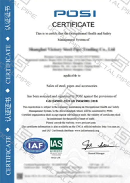
CE Certificate
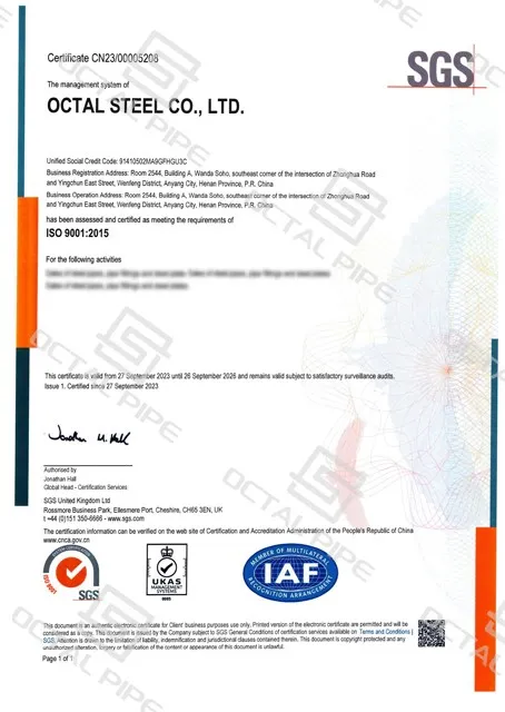
ISO 9001 Certificate
API Q1 Certificate
ABS Certificate
AP-5L Certificate
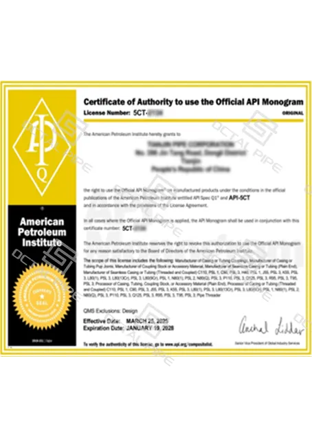
API-5CT Certificate