Most commissioning delays don't come from straight pipe runs. They come from interfaces-difficult fit-up, repeated weld repairs, bolt-hole misalignment, hydrotest leaks, and acceptance documents that don't line up. A reliable pipe connection and sealing outcome depends on two fundamentals: controllable joint geometry and repeatable sealing load.

Connection Methods And The Controls That Matter
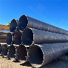
1. Welding connections-what really drives stability?
A stable welded joint comes from consistency across end preparation, fit-up, welding execution, and inspection. In the field, geometry variation and heat-input variation are what get amplified.
- End preparation consistency
If bevel angle, land, or end-face quality varies, root opening drifts and the weld window narrows. A common sign is inconsistent pass rates across the same line.
- Fit-up and alignment control
Root opening, internal mismatch, and ovality/concentricity directly affect root fusion and NDE results. Thin-wall, small OD, and short-piece assemblies are more sensitive.
- Heat-input window matched to material and thickness
Too low increases lack of fusion/penetration risk; too high increases distortion and can affect flange-face condition.
- Inspection and repair accessibility
If joints are crowded near supports, walls, valves, or equipment, NDE and repair access often becomes the real driver of schedule risk.
When a welded connection is tied to a flange, welding distortion can shift the issue from a weld-quality problem into a sealing problem-localized leakage caused by uneven gasket compression.
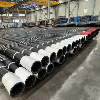
2. Socket/fillet welding-why assembly rules matter more than appearance
Socket-style joints often look fine visually, but stability depends heavily on repeatable assembly practice.
- Consistent insertion depth and shoulder gap
- Repeatable fillet weld geometry, especially in tight access areas
- Higher sensitivity to fatigue under cycling and vibration service
- Crevice-area cleanliness and corrosion behavior matched to the service environment
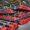
3. Threaded connections-reliability is an assembly discipline
Threaded joints are only as stable as the assembly standard behind them.
- Correct thread form and adequate engagement
- Damage control on thread surfaces
- Consistent sealant type and application method
- Defined tightening and re-check practice
- Clear anti-loosening logic under vibration and thermal cycling
What Controls Flange Sealing Performance?
Flange joints translate assembly quality directly into sealing results. Stable sealing requires three items to be controlled together: flange face condition, gasket working window, and repeatable bolt preload.
1. Flange face condition
- Flatness/waviness drives compression uniformity
- Surface finish affects gasket bite and recovery
- Nicks, dents, and corrosion become leak paths
- Welding distortion can create local over/under-compression
A typical field symptom is leakage concentrated on one side or around a few bolts, not an even seep around the full circumference.
2. Gasket working window
- Under-compression causes early leakage
- Over-compression crushes the gasket and reduces recovery, often worsening after thermal cycles
- Temperature and media accelerate creep/relaxation, reducing effective gasket stress over time
Upgrading the gasket alone has limited value if face condition or preload consistency is the real constraint.
3. Bolt preload consistency
- Different tightening sequences create uneven gasket stress
- Over-tightening can warp the face and reduce sealing stability
- Lubrication and friction variation make torque-to-preload inconsistent
- Thermal cycles and vibration reduce preload, often leading to early-life leaks
One Table: Acceptance Checkpoints By Connection Method
| Connection method | Assembly control points | Typical failure symptom | Acceptance / records usually checked |
|---|---|---|---|
| Welding | Bevel/end-face quality; root opening; internal mismatch/alignment; distortion control; NDE access | NDE failures and repairs; localized hydrotest leaks caused by uneven face compression | Visual & dimensional checks; NDT as required; pressure/leak test where applicable; weld/NDE traceable records |
| Socket/fillet | Insertion depth and shoulder gap; repeatable fillet geometry; weld & inspection access | Acceptable appearance but higher leak/fatigue risk; localized crevice issues | Assembly rule & sampling checks; visual and required inspection records; tests and documentation per project |
| Threaded | Thread form & engagement; damage control; sealant consistency; tightening & re-check rule | Early leakage or loosening over time, especially after rework | Thread & sealant consistency; assembly records where required; leak checks/tests per project |
A Practical On-Site Verification Order For Flange Joints
Step 1: Check the flange face first
- Visible damage: nicks, scratches, dents, corrosion spots
- Signs of uneven contact or distortion, especially after welding
- Leak location patterns that correlate to local face issues
Step 2: Verify gasket suitability and compression behavior
- Fit to media/temperature/cleaning regime
- Uneven imprint, localized crush, or abnormal deformation
- "Tighten more but still leaks" patterns that signal uneven compression or unstable preload
Step 3: Confirm preload repeatability
- Consistent tightening sequence and staged tightening
- Consistent lubrication and friction condition
- Awareness of preload loss risks under thermal cycling and vibration


Where Rework Usually Starts
- End prep not aligned with the welding procedure → geometry drift → repairs increase
- Fit-up/alignment not controlled → internal mismatch and unstable root → NDE failures
- Spool tolerance stack-up → bolt-hole misalignment → forced installation stress
- Welding distortion affects flange faces → uneven gasket stress → localized hydrotest leaks
- Tightening practice varies by crew → preload scatter → early-life leakage
A common chain reaction is forced alignment to make holes line up → uneven gasket compression → leak during test → more tightening → face distortion → recurring leak.
What acceptance typically focuses on
For pipe connection and sealing acceptance, reviewers usually look for items that are traceable, measurable, and verifiable:
- Traceability: heat/batch identification and certificates
- Interface-critical geometry: end condition, alignment, flange-face condition, bolt-hole alignment
- Required inspection and test records per project
- Documentation pack mapped consistently to the interface list
In Octal Pipe project deliveries, components and documents are often organized against a single interface list so connection logic, sealing approach, and acceptance records stay aligned and easier to audit.
FAQ
Certifications

CE Certificate

ISO 9001 Certificate

API Q1 Certificate

ABS Certificate

AP-5L Certificate

API-5CT Certificate