High-Strength Role of X70 in Pipeline Design
API 5L line pipe grades cover a wide strength range; X70 occupies the upper band where designers can still qualify practical field welding procedures. Many long-distance gas lines and export pipelines move to X70 mainly to cut wall thickness and steel tonnage without lowering design pressure. That combination of high strength and controllable weldability explains why X70 often replaces X60/X65 on new, high-capacity routes.Typical design drivers include:
- Higher operating pressure for long-distance gas transmission
- Lower pipeline weight on soft ground or difficult terrain
- Export lines linked to offshore developments where route length amplifies steel cost
- Looping or uprating existing corridors while keeping wall thickness within constructible limits
Once a project locks in X70, the material specification usually defines PSL level, welded product form and coating concept together, then adds NDT, documentation and construction requirements around that core choice.


Governing Standards and Product Levels
The reference document for API 5L X70 welded line pipe is the API 5L standard, aligned with ISO 3183. Project specifications most often call for one of these combinations:
- X70 PSL1 – welded line pipe for general transmission service
- X70 PSL2 – welded line pipe with tighter composition limits, toughness criteria and traceability
API 5L covers both seamless and welded products, but long-distance, large-diameter systems overwhelmingly rely on welded X70. For PSL2 welded pipe, project documents typically state:
- Delivery condition (TMCP or Q+T, depending on plate/coil route)
- Required Charpy impact temperature and absorbed energy
- NDT scope and frequency for weld seam and pipe body
- Traceability rules from steel heat to finished pipe, including test results and coating records
Mill procedures and inspection & test plans (ITPs) then translate these requirements into production steps and sampling plans.
Mechanical Property Profile and Design Notes
The characteristic feature of X70 is its specified minimum yield strength (SMYS) of 70,000 psi (≈ 485 MPa) under API 5L. This higher yield level is what lets designers reduce wall thickness compared with X60/X65 at the same design pressure.
Table 1 – Typical minimum mechanical properties (reference):
|
Grade |
PSL Level |
Min. Yield Strength SMYS (MPa) |
Min. Tensile Strength SMTS (MPa) |
Typical Elongation (%) |
|
X60 |
PSL1 / PSL2 |
≥ 415 |
≥ 520 |
≈ 21 |
|
X65 |
PSL1 / PSL2 |
≥ 450 |
≥ 535 |
≈ 20–22 |
|
X70 |
PSL1 / PSL2 |
≥ 485 |
≥ 570 |
≈ 18–21 |
High-strength design notes:
- Higher SMYS enables thinner walls at a given internal pressure, but design teams then pay closer attention to ovality, local buckling and external loads, especially for buried and offshore service.
- SMTS is combined with fracture control calculations to evaluate crack arrest behaviour, which is critical on long-distance gas lines.
- Elongation must remain sufficient for cold field bending, tie-ins and ground movement; many projects qualify bends and girth welds on representative X70 pipe before full production welding begins.
PSL2 X70 projects usually specify Charpy V-notch impact tests at a defined temperature. Heavy-wall and gas transmission lines often add DWTT (drop-weight tear tests) to support fracture propagation control.
Welded Manufacturing with LSAW as the Core Route
Manufacturing route plays a major role in how X70 performs once installed. In many large-diameter, high-pressure gas and oil projects, LSAW (SAWL) is treated as the primary option, while ERW/HFW and SSAW are used where their diameter and thickness capabilities match the design envelope.
1 LSAW / SAWL – Main Route for High-Strength Trunklines
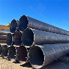
LSAW X70 pipe is produced from wide plate formed by UOE or JCO processes and welded using double-sided submerged arc welding. This combination supports large diameters and heavy walls, exactly the range needed for long gas trunklines and offshore export lines running at high pressure. Forming and welding parameters are set so that plate strength, weld strength and HAZ toughness all meet X70 requirements around the full circumference.
Typical LSAW X70 specification features include:
- Full-length UT for weld seam and pipe body, with RT in defined locations where required
- Stress-relief heat treatment on thick-wall sections to reduce residual stress and improve dimensional control
- Tight tolerances on out-of-roundness and straightness to support field bending and offshore installation
- Sampling locations defined in base metal, HAZ and weld metal for tensile and impact tests
This blend of high strength, wall-thickness capability and geometric accuracy explains why LSAW is often the first manufacturing route evaluated when a project specifies X70 for new trunklines.
2 ERW / HFW and SSAW – Complementary Routes
LSAW does not cover every diameter and wall-thickness combination. ERW/HFW and SSAW fill gaps and support regional applications:
ERW / HFW X70
- Produced from hot-rolled coil, slit and formed before high-frequency welding of a longitudinal seam.
- Applied mainly to small and medium diameters with moderate wall thickness in land-based systems, loops and station piping.
- Weld seam quality is monitored by online NDT (UT/EC); PSL2 specifications may call for local PWHT in the weld and HAZ.
SSAW / SAWH X70
- Manufactured from coil formed at a helical angle with inner and outer submerged arc welds.
- Offers good material utilisation in large diameters where spiral seams are acceptable to the design code and project specification.
- Normally delivered with full-length UT of the spiral weld, plus RT where the project demands additional assurance.
All routes are tuned so that weld and HAZ properties are not weaker than the X70 parent material, a key point when the grade is used at high stress levels.
3 UOE and JCOE Forming for X70 LSAW Pipe
Plate forming method has a direct impact on ovality control, residual stress distribution and overall dimensional stability. For X70 LSAW, both UOE and JCOE lines are widely used, and project teams sometimes ask how they compare from an engineering viewpoint.
Table 2 – Comparison of UOE vs. JCOE forming for X70 LSAW line pipe:
|
Feature |
UOE Forming |
JCOE Forming |
Typical Impact on X70 Projects |
|
Forming sequence |
U-press → O-press → Expansion |
J-press (multi-step) → C-press → O-press → Expansion |
More steps in JCOE give flexible control over different wall sizes |
|
Dimensional control |
Very good roundness after expansion |
Good roundness, often with slightly lower expansion |
UOE often favoured when strict ovality is specified |
|
Wall thickness range |
Strong for medium to heavy wall plates |
Also suitable for heavy wall with multi-step forming |
Both can support typical X70 trunkline wall thicknesses |
|
Residual stress pattern |
Expansion tends to homogenise stresses around the OD |
Stepwise forming spreads strain over several stages |
JCOE sometimes used when lower forming strain is preferred |
|
Production batch flexibility |
Efficient for large tonnages, limited size changes |
More adaptable to frequent diameter/thickness changes |
JCOE better for mixed-diameter or staged delivery projects |
|
Typical application focus |
Long, uniform mainline sections with tight tolerances |
Projects with varying sizes, staged route sections |
Both can meet X70 requirements when procedures are qualified |
Selection between UOE and JCOE usually depends more on mill configuration and project mix than on fundamental performance differences. Once forming, welding and expansion procedures are qualified to X70 requirements, both routes can deliver the high-strength, low-ovalisation pipe body needed for demanding trunkline service.


Chemistry Control for High-Strength Welded Line Pipe
X70 runs close to the upper end of typical pipeline stress, so the chemical design must deliver strength and toughness without closing off weldability. Carbon equivalent (CE) and microalloying levels are therefore defined within narrow bands.
Table 3 – Indicative composition ranges for welded API 5L X70 (PSL2, reference):
|
Element |
Typical Range (%) |
Role in X70 Welded Line Pipe |
|
C |
≈ 0.06–0.12 |
Provides base strength; kept low to preserve weldability |
|
Mn |
≈ 1.40–1.80 |
Supports strength and impact toughness |
|
P |
≤ 0.020–0.025 |
Lower phosphorus reduces brittle fracture risk |
|
S |
≤ 0.010–0.015 |
Low sulphur improves weld and HAZ performance |
|
Nb, V, Ti (total) |
≈ 0.03–0.10 |
Grain refinement and precipitation strengthening |
Typical PSL2 requirements for X70 welded pipe include:
- Upper limits for CEIIW and/or PCM to keep preheat and interpass requirements within a practical range
- Limits on total Nb+V+Ti and on individual microalloy contents
- Optional controls on Cu, Ni, Cr and Mo to match the medium and welding procedures
- Additional toughness and hardness criteria on heavy-wall sections or low-temperature routes
Such control becomes particularly important when high-strength X70 is combined with cold climates, elevated design factors or offshore integration.
Dimensional Range and Common Project Selections
Welded X70 can be supplied over a broad dimensional envelope. Mill capability sets absolute limits, but typical project selections fall within the ranges below.
Table 4 – Typical dimensional range for welded X70 line pipe (indicative):
|
Item |
Range / Description |
|
Outside Diameter |
Approx. 4" – 56" (≈ 114 – 1422 mm) |
|
Wall Thickness |
About 6 – 35 mm, driven by pressure and stability checks |
|
Length |
SRL / DRL, or project-specific cut-to-length |
|
End Finish |
Plain end (PE) or beveled end (BE) for field welding |
|
Straightness |
Commonly limited to ≈ 0.15 % of pipe length |
Designers of onshore high-pressure gas lines often combine large diameters with moderate wall thickness to balance capacity and welding productivity. X70 used on offshore export or landfall lines usually features thicker walls to resist external pressure, bending and installation loads, together with tighter limits on ovality and local geometric imperfections.
Coating systems-such as FBE, 3LPE, 3LPP and concrete weight coating-are then specified to address corrosion risk, on-bottom stability and thermal performance along the route.
Inspection, Testing and Welding Procedure Control
X70 operates at higher stress than lower grades, so inspection and testing are more comprehensive. A representative scheme for welded X70 pipe can be summarised as follows:
Table 5 – Example inspection and testing matrix for welded API 5L X70:
|
Category |
Typical Requirements for X70 Welded Pipe |
|
Hydrostatic test |
100 % of pipes, test pressure set by design code |
|
Weld seam NDT |
100 % UT / RT / EC depending on process and PSL level |
|
Pipe body NDT |
UT for LSAW/SSAW, additional checks per project spec |
|
Tensile tests |
Per heat and thickness range |
|
Charpy impact tests |
Required for PSL2 at agreed temperature and location |
|
DWTT |
Often specified for gas transmission and heavy walls |
|
Dimensional checks |
OD, wall, ovality, straightness, end geometry |
|
Coating inspection |
Holiday test and visual per coating specification |
Construction teams usually give extra attention to welding procedure qualification (WPS/PQR) when working with X70. Common focus points include:
- Heat input and interpass temperature limits
- Weld metal strength matching or slight overmatching vs. X70 base metal
- Hardness and HAZ toughness verification, especially for mechanised welding
- Control of misalignment, weld reinforcement and residual stress at girth welds
Well-qualified procedures and trained crews allow X70 joints to be installed at mainline production rates while still meeting stringent quality requirements.
Applications and Octal Pipe Supply Scope
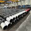
Pipeline owners often shortlist API 5L X70 welded line pipe when a single grade must combine high design pressure, long routing and manageable wall thickness. Common scenarios include new gas trunklines through remote regions, export and landfall lines tied to offshore fields, and uprated loops or replacement segments on existing corridors where both capacity and strength margins need to increase without excessive pipe weight.
Octal Pipe supports these projects with welded X70 to API 5L PSL1 and PSL2 in ERW/HFW, LSAW and SSAW forms, matching diameter, wall thickness, coating system and inspection scope to the project specification. Third-party witnessing by BV, DNV, SGS or other nominated bodies can be arranged so that high-strength X70 material records integrate cleanly into the overall pipeline design and QA/QC framework.
FAQ

01.What's the difference between API 5L X70 PSL1 and PSL2 for welded line pipe?
02.How do I choose ERW vs LSAW vs SSAW for API 5L X70 welded line pipe?
03.What should I request to verify API 5L X70 welded line pipe quality before purchase?
Certifications

CE Certificate

ISO 9001 Certificate

API Q1 Certificate

ABS Certificate

AP-5L Certificate

API-5CT Certificate