what is CWC?
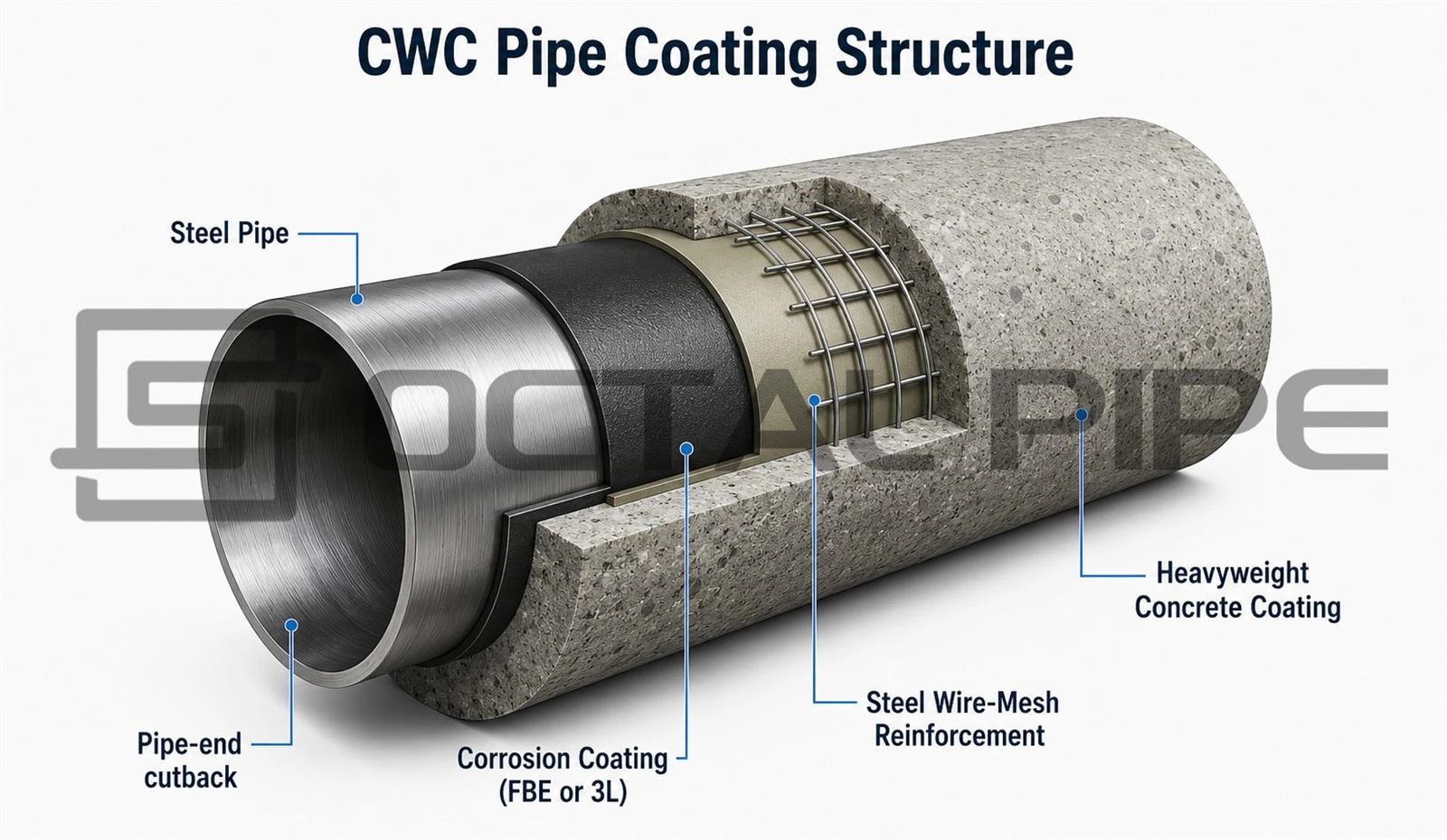
CWC is commonly used on subsea pipelines and water-crossing pipelines where the pipe needs negative buoyancy, better on-bottom stability and stronger resistance to handling, installation and seabed-contact damage. During production, the bare or pre-coated pipe is inspected, the reinforcement is positioned, and the concrete is batched to the specified density and strength before being applied by impingement or compression wrapping. The coated pipe is then formed with the required end cutbacks, cured, weighed and inspected before release. ISO 21809-5 covers the qualification, application, testing and handling of reinforced externa
The main design question is not only the concrete thickness. CWC because both affect concrete mass, submerged pipeline weight, finished outside diameter, hydrodynamic loading, reinforcement cover, pipe-joint weight and installation compatibility. A CWC coated pipe should therefore be specified from the pipeline stability design and verified through measurable production records, rather than selected only by referring to a previous project's coating thickness.
CWC Thickness and Density Selection Criteria
The practical selection sequence is:
Base pipe data → anti-corrosion coating geometry → installation condition → operating condition → required submerged weight → trial CWC thickness and density → stability verification → manufacturing review → inspection and release.
|
Selection question |
Main information required |
Result to confirm |
|
How much negative buoyancy is required? |
Pipe weight, internal contents, seawater density and stability analysis |
Required submerged weight |
|
Can a larger coated pipe be installed? |
Finished OD, roller clearance, clamp clearance and vessel limits |
Installation compatibility |
|
Is sufficient mechanical protection provided? |
Thickness, reinforcement position and concrete cover |
Handling and impact protection |
|
Can higher density reduce the finished OD? |
Aggregate source, mix qualification and plant capability |
Density–thickness balance |
|
How will production be accepted? |
Tolerances, test methods and inspection frequency |
Measurable acceptance criteria |
CWC Pipe Coating Structure
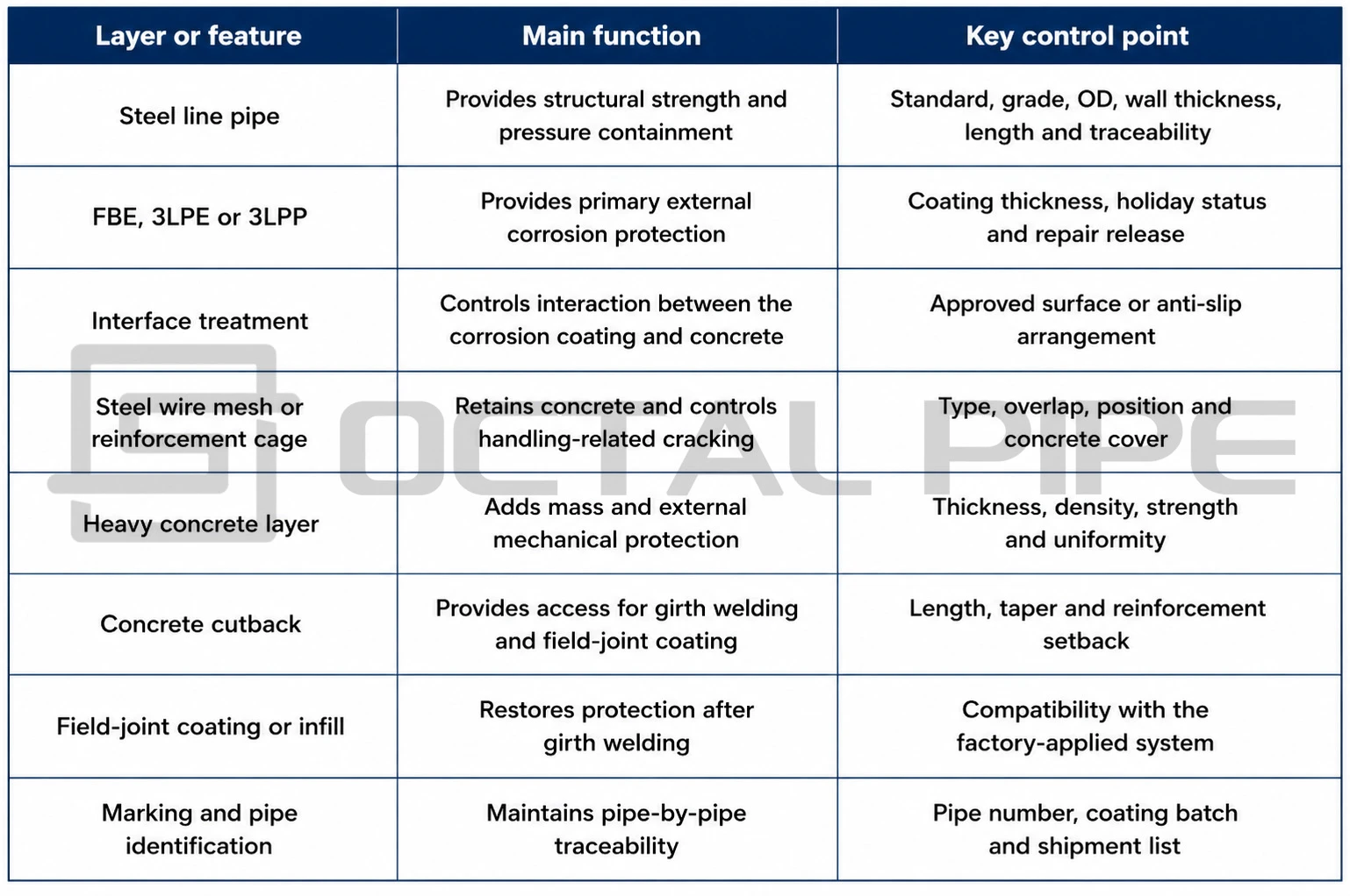
What CWC Thickness Controls
A greater thickness may improve mechanical protection and provide more space for reinforcement positioning. It also increases the coated diameter, concrete consumption and pipe-joint weight. These geometric changes must be included in the pipeline stability, handling and installation review.
The selected thickness should therefore satisfy three minimum conditions:
- Required concrete cover over the reinforcement
- Mechanical protection against handling and seabed contact
- Compatibility with rollers, clamps, tensioners and transport limits
What CWC Density Controls
A higher-density mix can be useful where additional submerged weight is required but installation-equipment clearance or hydrodynamic diameter must remain limited. Density, however, is a production-controlled material property rather than a purely theoretical design value.
The specified density must be supported by:
- Qualified heavyweight aggregate
- Controlled aggregate grading and moisture
- Verified batch proportions
- Fresh or hardened density testing
- Consistent application and curing
- Traceable batch-to-pipe records
Selecting the CWC Density–Thickness Combination
|
Governing project constraint |
Preferred design adjustment |
Required verification |
|
Additional submerged weight with limited finished OD |
Increase concrete density |
Mix qualification, density uniformity and joint weighing |
|
Greater impact or abrasion protection |
Increase coating thickness |
Reinforcement cover, handling performance and finished OD |
|
Restricted roller or clamp clearance |
Increase density before increasing thickness |
Maximum coated OD and installation-equipment compatibility |
|
Minimum reinforcement cover not achieved |
Increase thickness |
Mesh position and concrete-cover inspection |
|
Excessive pipe-joint weight |
Reduce thickness or optimise density |
Lifting, vessel and transport limits |
|
High hydrodynamic loading |
Limit unnecessary OD increase |
Revised stability and wave/current calculation |
|
Limited heavyweight aggregate availability |
Use a practical density with revised thickness |
Material source and coating-plant capability |
Selection Boundary
The selected combination should satisfy all of the following:
- Required submerged weight
- Minimum reinforcement cover
- Mechanical-protection requirement
- Maximum finished outside diameter
- Maximum allowable pipe-joint weight
- Coating-plant production capability
- Installation and handling limits

CWC Pipe Coating Process
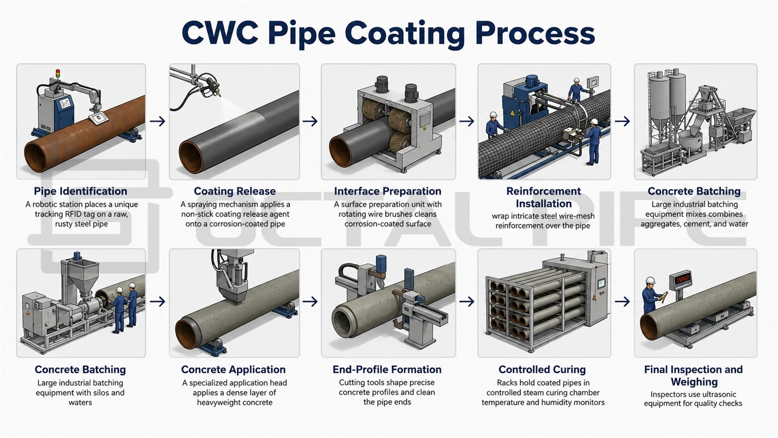
1. Pipe Identification and Incoming Inspection
The pipe number, heat number, grade, OD, wall thickness, length and anti-corrosion coating are checked against the production list.
Key controls include:
Pipe and MTC traceability
Pipe-end and bevel protection
Coating condition and repair status
2. Anti-Corrosion Coating Release
The FBE, 3LPE or 3LPP layer is inspected before concrete application.
The release inspection may include:
Visual condition
Holiday testing
Coating thickness
Repair verification
Pipe-end and marking checks
The inspection scope should follow the applicable coating standard, purchase order, project specification or approved ITP.
3. Interface Preparation
The approved interface is prepared between the anti-corrosion coating and the concrete layer.
Depending on the design, it may include:
Roughened surface treatment
Anti-slip arrangement
Bonding layer
Separation or cushioning layer
The interface system must follow the qualified coating procedure.
4. Reinforcement Installation
Steel wire mesh or reinforcement cages are positioned around the pipe before concrete application.
Inspection should confirm:
Reinforcement type and configuration
Overlap and number of layers
Position and concrete cover
End setback and installation stability
Incorrect positioning can reduce protective cover or expose reinforcement after handling damage.
5. Concrete Batching
Cement, water, graded aggregate, heavyweight aggregate and approved admixtures are proportioned through a controlled batching system.
The batch record should identify:
Material batches
Approved mix design
Moisture and water correction
Mixing time
Density-test sample
Pipe joints coated from the batch
The specification should state whether density refers to fresh, as-applied or hardened concrete.
6. Concrete Application
Concrete is commonly applied by impingement or compression wrapping.
The qualified process should match:
Pipe diameter
Coating thickness and density
Reinforcement arrangement
Anti-corrosion coating
Application speed
End-cutback design
7. Thickness and End-Profile Formation
The concrete is formed to the specified thickness, finished OD and end geometry.
Key dimensions include:
Concrete cutback
Reinforcement setback
Taper or chamfer
Welding access
Field-joint coating space
Incorrect end geometry can interfere with girth welding, clamps and field-joint completion.
8. Curing
The coated pipe is cured under the approved time and environmental conditions.
Handling should begin only after the required release condition is achieved to avoid:
Cracking
Spalling
Edge damage
Reinforcement displacement
Support-point damage
9. Final Inspection and Pipe-Joint Weighing
Each CWC coated pipe is inspected before release.
Final checks normally cover:
Pipe identity
Concrete thickness and finished OD
Pipe-joint weight
Cutback dimensions
Cracking, spalling and exposed reinforcement
Repairs and marking
Packing-list traceability
ISO 21809-5 covers the qualification, application, testing and handling of reinforced concrete coatings applied to bare or pre-coated pipe. Project-specific tolerances, test methods and inspection frequencies should still be defined in the purchase specification and approved ITP.
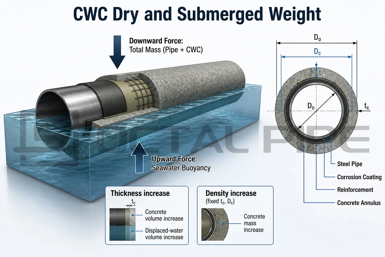
How CWC Thickness and Density Affect Pipe Weight
However, increasing thickness also enlarges the finished pipe diameter and displaces more seawater. For this reason, thickness and density should be calculated together when checking both dry weight and submer.
For one metre of pipe, the approximate concrete volume is:

Where:
Vc= concrete volume per metre
Dc = finished outside diameter after CWC
D0= outside diameter before CWC
The concrete mass per metre is:

Where:
mc = concrete mass per metre
ρc = concrete density
The approximate submerged contribution of the concrete layer is:

Where:
mc,sub = net submerged mass contribution
ρsw = seawater density
- Greater thickness → more concrete volume
- Higher density → more mass in the same volume
- Submerged contribution → concrete mass minus displaced seawater

The final pipeline weight model should also include:
- Steel pipe
- Anti-corrosion coating
- Reinforcement
- Cutbacks
- Field-joint coating or infill
- Anodes and attachments
- Internal water or transported product
- Marine growth allowance where specified
- Manufacturing tolerances
Theoretical calculations should be confirmed against actual pipe-joint weighing after coating and curing.
Illustrative CWC Weight Calculation
|
Parameter |
Value |
|
Pre-CWC outside diameter |
0.768 m |
|
CWC thickness |
75 mm |
|
Finished coated diameter |
0.918 m |
|
Concrete density |
3,200 kg/m³ |
|
Seawater density |
1,025 kg/m³ |
0.1986 m3/m
The theoretical concrete mass is:
635.6 kg/m
The simplified net submerged contribution of the concrete layer is:
432.0 kg/m
This is not the final submerged weight of the pipeline. The calculation must still include the steel pipe, anti-corrosion coating, reinforcement, internal contents, field joints, anodes, cutbacks and project tolerances.
Project Conditions That Govern CWC Design
A technically complete review should connect each project condition to its effect on submerged weight, finished diameter, pipe-joint weight and coating performance.
|
Project condition |
Why it matters |
Effect on CWC selection |
Required confirmation |
|
Empty, flooded or product-filled pipe |
Internal contents change the submerged weight of the pipeline |
The lightest condition may require more CWC mass |
Weight calculation for each design condition |
|
Pipe OD and wall thickness |
Steel mass and displaced-water volume change with pipe geometry |
Larger OD does not automatically mean greater stability |
Verified steel-pipe dimensions and unit weight |
|
Wave and current loading |
Hydrodynamic forces act on the finished coated diameter |
Greater CWC thickness may add weight but also increase loading |
Stability analysis using final coated OD |
|
Seabed soil and embedment |
Soil resistance helps control lateral movement |
Lower soil resistance may require greater submerged weight |
Geotechnical data and pipe–soil model |
|
Trenching, burial or rock dumping |
Secondary stabilisation can reduce reliance on CWC |
Temporary exposed conditions may still govern |
Installation sequence and temporary-condition review |
|
Installation method |
S-lay, J-lay and shore pull create different handling limits |
Pipe-joint weight and finished OD may limit the coating design |
Vessel, roller, clamp and lifting limits |
|
Corrosion-coating system |
FBE, 3LPE or 3LPP changes the pre-CWC diameter and interface |
Affects concrete volume, application procedure and field-joint design |
Approved coating and interface procedure |
|
Reinforcement and cover |
Mesh or cage position requires sufficient concrete depth |
Minimum thickness may be controlled by protection rather than weight |
Reinforcement drawing and cover inspection |
|
Cutbacks and field joints |
Factory concrete does not cover the complete pipe length |
Average line weight may be lower than the full-body calculation |
Cutback length and field-joint infill details |
|
Plant production capability |
Not every thickness-density combination is repeatable |
Theoretical designs may require adjustment for manufacturing control |
Qualified mix, process trial and production records |
Pipeline Operating Conditions
Installation → Flooding → Hydrotest → Normal Operation → Shutdown → Decommissioning.
For this reason, CWC thickness and density should be selected against the condition with the lowest confirmed stability margin. The review should compare submerged weight, final coated diameter, wave and current loading, pipe–soil resistance and temporary installation conditions before the coating design is released.
Final Coated Diameter and Stability Performance
For this reason, CWC thickness should not be selected from added weight alone. The stability assessment must use the final coated outside diameter, not the bare-pipe OD, because the coated diameter controls the effective geometry used in hydrodynamic and on-bottom stability calculations. Using the bare-pipe diameter can underestimate environmental loading.
The final coated diameter also affects several connected design factors:
- Hydrodynamic loading: a larger diameter generally increases the projected area exposed to waves and currents.
- Submerged weight efficiency: added thickness increases concrete mass, but it also increases seawater displacement.
- Pipe–soil interaction: seabed resistance and lateral stability depend on the final pipe geometry and contact condition.
- Installation compatibility: a larger coated OD and heavier pipe joint may affect rollers, clamps, tensioners, lifting equipment and vessel limits.
Where additional submerged weight is required but the maximum coated OD is restricted, increasing CWC density may be more effective than adding thickness. Where reinforcement cover, abrasion resistance or impact protection governs, greater thickness may still be necessary.
Installation Constraints on CWC Design
The following limits should be checked before the design is released:
- Maximum pipe-joint weight
- Roller and tensioner clearance
- Clamp compatibility
- Stinger and vessel capacity
- Lifting-point loading
- Stacking and transport limits
- Field-joint access
- Permitted coating damage during handling
Where the finished diameter is restricted, a higher-density mix may be preferred. Where reinforcement cover or impact resistance controls the design, greater thickness may still be required.
CWC Selection by Pipeline Condition
Exposed Subsea Pipeline
For a pipeline placed directly on the seabed, the CWC design is closely linked to vertical and lateral stability.
The analysis should consider:
Wave and current loading
Submerged pipe weight
Pipe–soil resistance
Initial penetration
Pipeline contents
Scour
Finished hydrodynamic diameter
Increasing thickness adds mass, but it can also increase environmental loading by enlarging the coated diameter. Both effects should be included in the same calculation.
Trenched or Buried Pipeline
A buried pipeline may obtain additional restraint from soil and backfill. However, the pipe can remain exposed during installation, flooding, pre-backfill or scour conditions.
The temporary condition may therefore govern CWC selection even when the final pipeline is buried.
Deepwater Pipeline
Water depth alone does not determine the required concrete thickness.
A deepwater review should also address:
Installation tension
Pipe-joint weight
Vessel capability
Stinger reaction
Empty and flooded conditions
Handling load
Finished coated diameter
A higher-density mix may be considered where additional mass is required without an excessive increase in diameter.
Landfall and Shore-Pull Section
Landfall pipe can experience:
Roller contact
Pulling loads
Tidal abrasion
Repeated handling
Shoreline impact
Local seabed irregularities
Mechanical protection, reinforcement and end geometry can be as important as negative buoyancy in these sections.
River, Swamp and Waterlogged Soil
CWC coated pipe can also be used where groundwater, floodwater or buoyant soil creates uplift risk.
The design should review:
Groundwater level
Flood condition
Burial depth
Soil buoyancy
Backfill
Scour
Pipeline contents
Seasonal operating state
An offshore seawater calculation should not automatically be reused for a river or swamp crossing.
CWC Pipe Specification and Ordering Data
|
Specification item |
Information to state |
Why it matters |
|
Base pipe |
Standard and edition, grade, PSL, manufacturing method, OD, WT, length and quantity |
Establishes the steel-pipe weight, pre-coating geometry and traceability basis |
|
Anti-corrosion system |
FBE, 3LPE, 3LPP or project-specific coating, including nominal thickness and repair status |
Defines the diameter and surface condition before CWC application |
|
CWC design basis |
Required submerged weight, applicable pipeline condition and approved stability calculation |
Determines the mass that the CWC system must provide |
|
Thickness and density |
Nominal thickness, concrete density, test condition and permitted tolerances |
Controls concrete volume, coated OD and pipe-joint weight |
|
Reinforcement and concrete |
Mesh or cage arrangement, cover, compressive strength, absorption and approved mix requirements |
Controls cracking resistance, handling performance and production consistency |
|
Finished pipe geometry |
Maximum coated OD, pipe-joint weight range, cutback, taper and reinforcement setback |
Confirms compatibility with laying equipment, welding and field-joint coating |
|
Field-joint and anode details |
Field-joint coating, concrete infill and anode location where applicable |
Prevents interference between factory coating, welding and offshore installation |
|
Inspection and documentation |
Test frequency, hold points, witness points, density and strength reports, dimensional records and pipe-by-pipe weight list |
Connects the delivered pipes to measurable acceptance evidence |
|
Handling and delivery |
Lifting method, support spacing, stacking, storage, end protection and transport restrictions |
Reduces cracking, spalling and coating damage before installation |
Acceptance Values to Define
The purchase specification should clearly separate:
- Nominal design values used for engineering calculations
- Manufacturing tolerances permitted during production
- Individual pipe-joint limits for thickness, OD and weight
- Lot-based test results for density, strength and absorption
- Repair acceptance criteria and required reinspection
- Concession procedure for results outside the specified limits
Inspection and Acceptance of CWC Coated Pipe
|
Inspection item |
Verification method |
What it confirms |
Record required |
|
Pipe identity |
Marking and pipe-list review |
Correct base pipe |
Incoming inspection record |
|
Anti-corrosion coating |
Visual and specified testing |
Pre-coating release |
Coating release report |
|
Reinforcement |
Position, overlap and cover check |
Approved reinforcement configuration |
Reinforcement record |
|
Raw materials |
Certificate and batch review |
Approved material source |
Material certificates |
|
Mix proportions |
Batching-system review |
Approved concrete mix |
Batch sheet |
|
Concrete density |
Approved density test |
Mass per defined volume |
Density report |
|
CWC thickness |
Circumferential measurement |
Specified concrete build-up |
Dimensional report |
|
Finished OD |
OD or circumference measurement |
Installation compatibility |
Dimensional report |
|
Pipe-joint weight |
Calibrated weighing system |
Actual delivered mass |
Pipe-by-pipe weight list |
|
Compressive strength |
Approved specimen test |
Concrete mechanical performance |
Laboratory report |
|
Water absorption |
Approved test when required |
Porosity-related performance |
Test report |
|
Cutback |
Dimensional inspection |
Welding and field-joint access |
End-inspection report |
|
Visual condition |
Crack, spalling and reinforcement inspection |
Final coating condition |
Final inspection report |
|
Repairs |
Approved procedure and reinspection |
Restored acceptance condition |
Repair log |
|
Final identity |
Pipe number and packing-list comparison |
Shipment traceability |
Final release dossier |
Recommended Traceability Chain
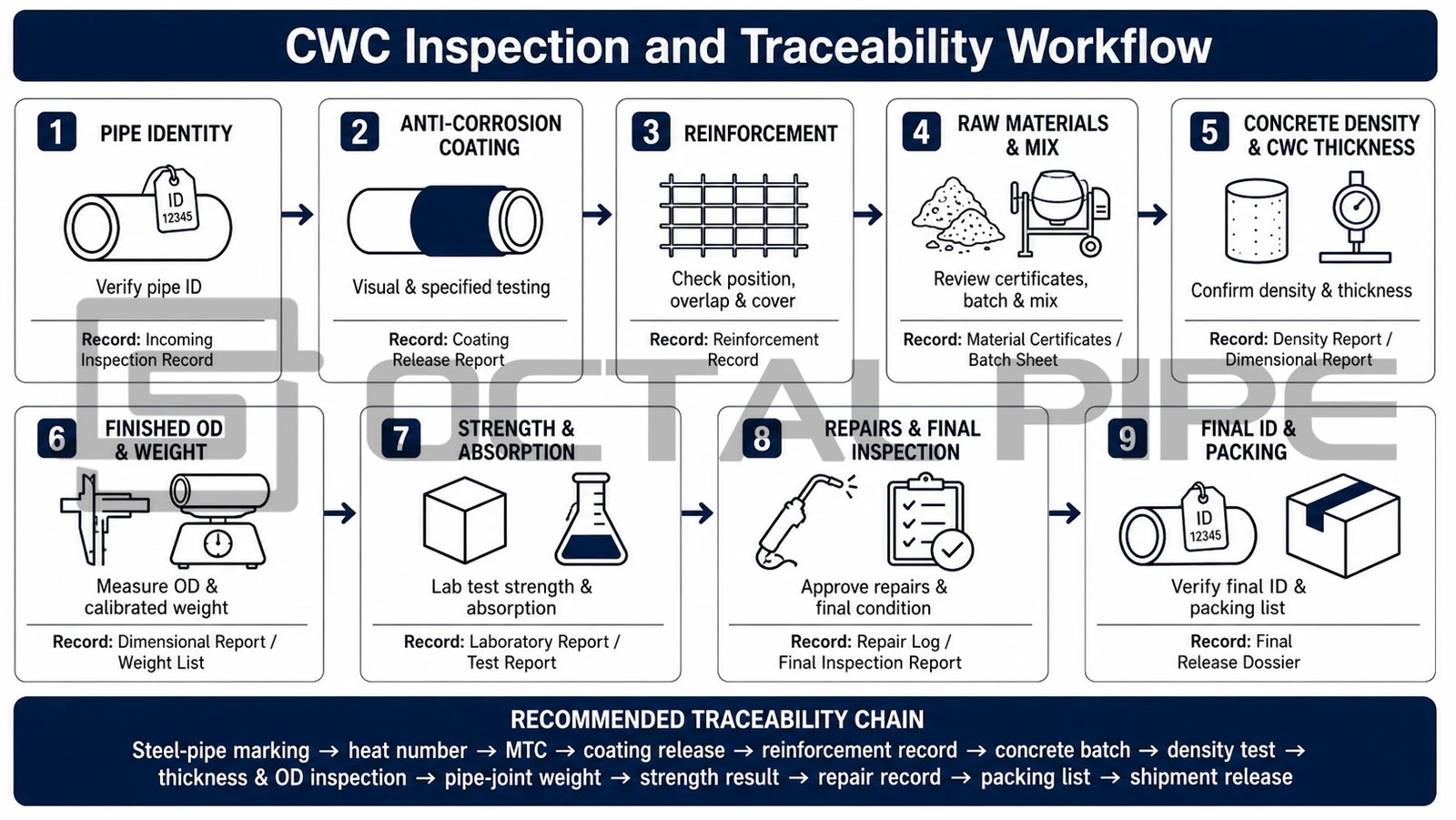
This chain links the delivered pipe to its base material, coating materials, production batch, inspection results and shipping identity.
Applicable Standards for CWC Design and Supply
DNV-RP-F109 provides guidance for submarine-pipeline on-bottom stability design. The project specification should identify the applicable edition and amendment level.
API Specification 5L defines the requirements for the steel line pipe beneath the CWC system. The purchase order should clearly state the applicable API 5L edition.
Final CWC Selection Considerations
Increasing density can add mass without enlarging the coated OD, but it requires a qualified and repeatable heavyweight-concrete mix. Increasing thickness can add both mass and protective depth, but it also increases pipe-joint weight, displaced-water volume and hydrodynamic diameter.
Required submerged weight → selected thickness and density → qualified CWC pipe coating process → pipe-joint dimensional and weight verification → inspection records → shipment traceability.
FAQ

01. What does CWC pipe mean?
02.What is CWC pipe coating used for?
03.What is the minimum CWC thickness?
04.Is higher CWC density always better?
05.Can greater CWC thickness replace higher concrete density?
Certifications

CE Certificate

ISO 9001 Certificate

API Q1 Certificate

ABS Certificate

AP-5L Certificate

API-5CT Certificate